REER-Mosaic Manual
MOSAIC - Installation and use manual
MOSAIC - Installation and use manual

You also want an ePaper? Increase the reach of your titles
YUMPU automatically turns print PDFs into web optimized ePapers that Google loves.
MODULAR SAFETY INTEGRATED CONTROLLER MOSAIC<br />
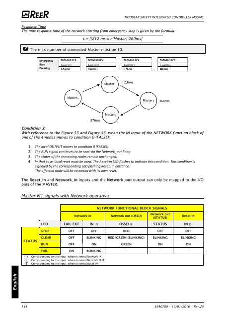
Response Time<br />
The max response time of the network starting from emergency stop is given by the formula:<br />
t r = [(212 ms x n°Master)-260ms]<br />
The max number of connected Master must be 10.<br />
Emergency<br />
Stop<br />
Pressing<br />
MASTER n°1 MASTER n°2 MASTER n°3 MASTER n°4<br />
t rMASTER1 t rMASTER2 t rMASTER3 t rMASTER4<br />
12,6ms 164ms 376ms 488ms<br />
Master1<br />
12,6ms<br />
Master 4<br />
Master 2<br />
164ms<br />
Master 3<br />
376ms<br />
With reference to the Figure 55 and Figure 56, when the IN input of the NETWORK function block of<br />
one of the 4 nodes moves to condition 0 (FALSE):<br />
1. The local OUTPUT moves to condition 0 (FALSE);<br />
2. The RUN signal continues to be sent via the Network_out lines;<br />
3. The states of the remaining nodes remain unchanged;<br />
4. In that case, local reset must be used. The Reset-in LED flashes to indicate this condition. This condition is<br />
signaled by the corresponding LED flashing Reset_In entrance.<br />
The affected node will be restarted with its own reset.<br />
The and inputs and the output can only be mapped to the I/O<br />
pins of the MASTER.<br />
Master M1 signals with Network operative<br />
(1) (2) (3)<br />
(1) Corresponding to the input where is wired Network IN<br />
(2) Corresponding to the input where is wired Network OUT<br />
(3) Corresponding to the input where is wired Reset IN<br />
English<br />
134 8540780 • 12/01/2016 • Rev.25


![BRESIMAR(asaTek)-Beckhoff-Livro Formação Técnica TwinCAT 2-v1.2_2009 [pt]](https://img.yumpu.com/62853104/1/190x245/bresimarasatek-beckhoff-livro-formacao-tecnica-twincat-2-v12-2009-pt.jpg?quality=85)