REER-Mosaic Manual
MOSAIC - Installation and use manual
MOSAIC - Installation and use manual

You also want an ePaper? Increase the reach of your titles
YUMPU automatically turns print PDFs into web optimized ePapers that Google loves.
MODULAR SAFETY INTEGRATED CONTROLLER MOSAIC<br />
WARNING: If the <strong>Manual</strong> Reset is active, a consecutive Input have to be used.<br />
Example : Input 1 and Input 2 are used for the fuctional block, then Input 3 have to<br />
be used for the Reset Input.<br />
Output test: This is used to select which test output signals are to be sent to the<br />
component contacts. This additional control permits detection and management of any<br />
short-circuits between the lines. To enable this control, the test output signals must be<br />
configured (amongst those available).<br />
Test at start-up: If selected this enables the test at start-up of the external component.<br />
This test is performed by opening the mobile guard or safety gate to run a complete<br />
function test and enable the output. This test is only requested at machine start-up (when<br />
the unit is switched on).<br />
Filter (ms): This is used to filter the signals coming from the external contacts. The filter<br />
can be configured to between 3 and 250 ms and eliminates any bouncing on the<br />
contacts. The length of the filter affects the calculation of the unit's total response time.<br />
Enable Error Out: If selected reports a fault detected by the function block.<br />
Item description: This allows a description of the component's function to be entered. The<br />
text is displayed in the top part of the symbol.<br />
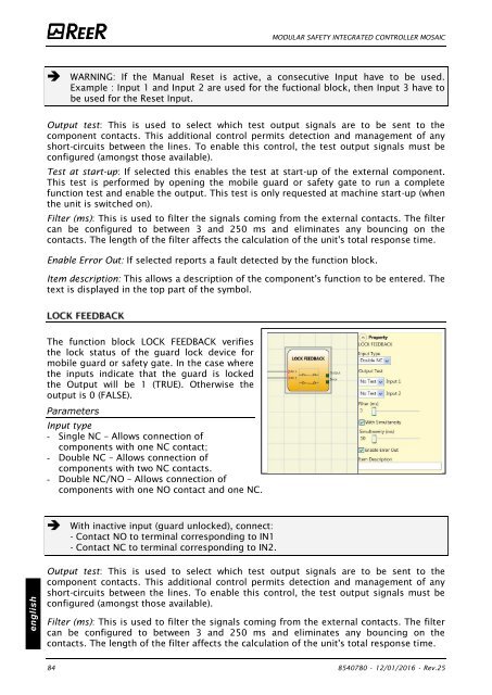
The function block LOCK FEEDBACK verifies<br />
the lock status of the guard lock device for<br />
mobile guard or safety gate. In the case where<br />
the inputs indicate that the guard is locked<br />
the Output will be 1 (TRUE). Otherwise the<br />
output is 0 (FALSE).<br />
Parameters<br />
Input type<br />
- Single NC – Allows connection of<br />
components with one NC contact;<br />
- Double NC – Allows connection of<br />
components with two NC contacts.<br />
- Double NC/NO – Allows connection of<br />
components with one NO contact and one NC.<br />
With inactive input (guard unlocked), connect:<br />
- Contact NO to terminal corresponding to IN1<br />
- Contact NC to terminal corresponding to IN2.<br />
english<br />
Output test: This is used to select which test output signals are to be sent to the<br />
component contacts. This additional control permits detection and management of any<br />
short-circuits between the lines. To enable this control, the test output signals must be<br />
configured (amongst those available).<br />
Filter (ms): This is used to filter the signals coming from the external contacts. The filter<br />
can be configured to between 3 and 250 ms and eliminates any bouncing on the<br />
contacts. The length of the filter affects the calculation of the unit's total response time.<br />
84 8540780 • 12/01/2016 • Rev.25


![BRESIMAR(asaTek)-Beckhoff-Livro Formação Técnica TwinCAT 2-v1.2_2009 [pt]](https://img.yumpu.com/62853104/1/190x245/bresimarasatek-beckhoff-livro-formacao-tecnica-twincat-2-v12-2009-pt.jpg?quality=85)