REER-Mosaic Manual
MOSAIC - Installation and use manual
MOSAIC - Installation and use manual

You also want an ePaper? Increase the reach of your titles
YUMPU automatically turns print PDFs into web optimized ePapers that Google loves.
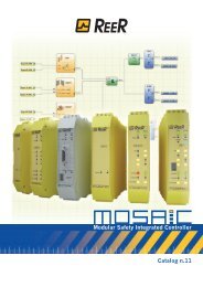
MODULAR SAFETY INTEGRATED CONTROLLER MOSAIC<br />
Output test: This is used to select which test output signals are to be sent to the switch.<br />
This additional control permits detection and management of any short-circuits between<br />
the lines. To enable this control, the test output signals must be configured (amongst<br />
those available).<br />
Test at start-up: If selected this enables the test at start-up of the switch. This test is<br />
performed by opening and closing the switch contact to run a complete function test and<br />
enable the output. This test is only requested at machine start-up (when the unit is<br />
switched on).<br />
Filter (ms): This is used to filter the signals coming from the switch. The filter can be<br />
configured to between 3 and 250ms and eliminates any bouncing on the contacts. The<br />
length of the filter affects the calculation of the unit's total response time.<br />
Enable Error Out: If selected reports a fault detected by the function block.<br />
Item description: This allows a description of the component's function to be entered. The<br />
text is displayed in the top part of the symbol.<br />
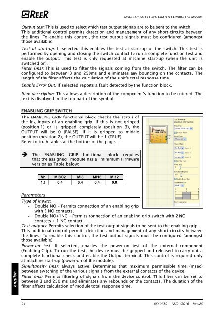
The ENABLING GRIP functional block checks the status of<br />
the Inx inputs of an enabling grip. If this is not gripped<br />
(position 1) or is gripped completely (position 3), the<br />
OUTPUT will be 0 (FALSE). If it is gripped to middle<br />
position (position 2), the OUTPUT will be 1 (TRUE).<br />
Refer to truth tables at the bottom of the page.<br />
The ENABLING GRIP functional block requires<br />
that the assigned module has a minimum Firmware<br />
version as Table below:<br />
M1 MI8O2 MI8 MI16 MI12<br />
1.0 0.4 0.4 0.4 0.0<br />
english<br />
Parameters<br />
Type of inputs:<br />
- Double NO – Permits connection of an enabling grip<br />
with 2 NO contacts.<br />
- Double NO+1NC – Permits connection of an enabling grip switch with 2 O<br />
contacts + 1 NC contact.<br />
Test outputs: Permits selection of the test output signals to be sent to the enabling grip.<br />
This additional control permits detection and management of any short-circuits between<br />
the lines. To enable this control, the test output signals must be configured (amongst<br />
those available).<br />
Power-on test: If selected, enables the power-on test of the external component<br />
(Enabling Grip). To run the test, the device must be gripped and released to carry out a<br />
complete functional check and enable the Output terminal. This control is required only<br />
at machine start-up (power-on of the module).<br />
Simultaneity (ms): always active. Determines that maximum permissible time (msec)<br />
between switching of the various signals from the external contacts of the device.<br />
Filter (ms): Permits filtering of signals from the device control. This filter can be set to<br />
between 3 and 250 ms and eliminates any rebounds on the contacts. The duration of the<br />
filter affects calculation of module total response time.<br />
94 8540780 • 12/01/2016 • Rev.25


![BRESIMAR(asaTek)-Beckhoff-Livro Formação Técnica TwinCAT 2-v1.2_2009 [pt]](https://img.yumpu.com/62853104/1/190x245/bresimarasatek-beckhoff-livro-formacao-tecnica-twincat-2-v12-2009-pt.jpg?quality=85)