REER-Mosaic Manual
MOSAIC - Installation and use manual
MOSAIC - Installation and use manual

Create successful ePaper yourself
Turn your PDF publications into a flip-book with our unique Google optimized e-Paper software.
MODULAR SAFETY INTEGRATED CONTROLLER MOSAIC<br />
GUARD LOCK OPERATORS (max number = 4)<br />
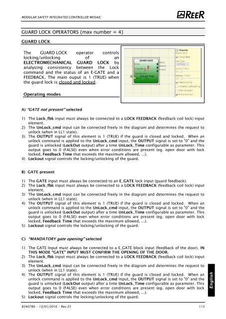
The GUARD LOCK operator controls<br />
locking/unlocking of an<br />
by<br />
analysing consistency between the Lock<br />
command and the status of an E-GATE and a<br />
FEEDBACK. The main ouput is 1 (TRUE) when<br />
the guard lock is closed and locked.<br />
1) The input must always be connected to a (feedback coil lock) input<br />
element.<br />
2) The input can be connected freely in the diagram and determines the request to<br />
unlock (when in LL1 state).<br />
3) The signal of this element is 1 (TRUE) if the guard is closed and locked. When an<br />
unlock command is applied to the input, the signal is set to "0" and the<br />
guard is unlocked ( output) after a time configurable as parameter. This<br />
output goes to 0 (FALSE) even when error conditions are present (eg. open door with lock<br />
locked, that exceeds the maximum allowed, ...).<br />
4) signal controls the locking/unlocking of the guard.<br />
1) The input must always be connected to an lock input (guard feedback).<br />
2) The input must always be connected to a (feedback coil lock) input<br />
element.<br />
3) The input can be connected freely in the diagram and determines the request to<br />
unlock (when in LL1 state).<br />
4) The signal of this element is 1 (TRUE) if the guard is closed and locked. When an<br />
unlock command is applied to the input, the signal is set to "0" and the<br />
guard is unlocked ( output) after a time configurable as parameter. This<br />
output goes to 0 (FALSE) even when error conditions are present (eg. open door with lock<br />
locked, that exceeds the maximum allowed, ...).<br />
5) signal controls the locking/unlocking of the guard.<br />
1) The GATE Input must always be connected to a E_GATE block input (feedback of the door).<br />
2) The input must always be connected to a (feedback coil lock) input<br />
element.<br />
3) The input can be connected freely in the diagram and determines the request to<br />
unlock (when in LL1 state).<br />
4) The signal of this element is 1 (TRUE) if the guard is closed and locked. When an<br />
unlock command is applied to the input, the signal is set to "0" and the<br />
guard is unlocked ( output) after a time configurable as parameter. This<br />
output goes to 0 (FALSE) even when error conditions are present (eg. open door with lock<br />
locked, that exceeds the maximum allowed, ...).<br />
5) signal controls the locking/unlocking of the guard.<br />
English<br />
8540780 • 12/01/2016 • Rev.25 115


![BRESIMAR(asaTek)-Beckhoff-Livro Formação Técnica TwinCAT 2-v1.2_2009 [pt]](https://img.yumpu.com/62853104/1/190x245/bresimarasatek-beckhoff-livro-formacao-tecnica-twincat-2-v12-2009-pt.jpg?quality=85)