REER-Mosaic Manual
MOSAIC - Installation and use manual
MOSAIC - Installation and use manual

You also want an ePaper? Increase the reach of your titles
YUMPU automatically turns print PDFs into web optimized ePapers that Google loves.
MODULAR SAFETY INTEGRATED CONTROLLER MOSAIC<br />
OUT STATUS<br />
The OUT STATUS signal is a Programmable signal output that can indicate the status of:<br />
• An input.<br />
• An output.<br />
• A node of the logic diagram designed using the MSD.<br />
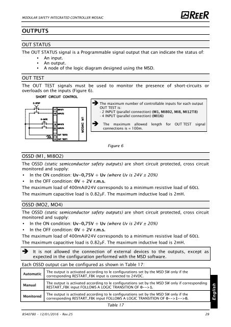
OUT TEST<br />
The OUT TEST signals must be used to monitor the presence of short-circuits or<br />
overloads on the inputs (Figure 6).<br />
The maximum number of controllable inputs for each output<br />
OUT TEST is:<br />
- 2 INPUT (parallel connection)<br />
- 4 INPUT (parallel connection)<br />
The maximum allowed length for OUT TEST signal<br />
connections is = 100m.<br />
Figure 6<br />
OSSD (M1, MI8O2)<br />
The OSSD (static semiconductor safety outputs) are short circuit protected, cross circuit<br />
monitored and supply:<br />
• In the ON condition: (where Uv is 24V ± 20%)<br />
• In the OFF condition:<br />
The maximum load of 400mA@24V corresponds to a minimum resistive load of 60.<br />
The maximum capacitive load is 0.82F. The maximum inductive load is 2mH.<br />
OSSD (MO2, MO4)<br />
The OSSD (static semiconductor safety outputs) are short circuit protected, cross circuit<br />
monitored and supply:<br />
• In the ON condition: (where Uv is 24V ± 20%)<br />
• In the OFF condition:<br />
The maximum load of 400mA@24V corresponds to a minimum resistive load of 60.<br />
The maximum capacitive load is 0.82F. The maximum inductive load is 2mH.<br />
It is not allowed the connection of external devices to the outputs, except as<br />
expected in the configuration performed with the MSD software.<br />
Each OSSD output can be configured as shown in Table 17:<br />
The output is activated according to le configurations set by the MSD SW only if the<br />
corresponding RESTART_FBK input is conected to 24VDC.<br />
The output is activated according to le configurations set by the MSD SW only if corresponding<br />
RESTART_FBK input FOLLOWS A LOGIC TRANSITION OF<br />
The output is activated according to le configurations set by the MSD SW only if the<br />
corresponding RESTART_FBK input FOLLOWS A LOGIC TRANSITION OF<br />
English<br />
Table 17<br />
8540780 • 12/01/2016 • Rev.25 29


![BRESIMAR(asaTek)-Beckhoff-Livro Formação Técnica TwinCAT 2-v1.2_2009 [pt]](https://img.yumpu.com/62853104/1/190x245/bresimarasatek-beckhoff-livro-formacao-tecnica-twincat-2-v12-2009-pt.jpg?quality=85)