REER-Mosaic Manual
MOSAIC - Installation and use manual
MOSAIC - Installation and use manual

You also want an ePaper? Increase the reach of your titles
YUMPU automatically turns print PDFs into web optimized ePapers that Google loves.
MODULAR SAFETY INTEGRATED CONTROLLER MOSAIC<br />
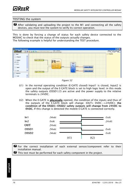
TESTING the system<br />
After validating and uploading the project to the M1 and connecting all the safety<br />
devices, you must test the system to verify its correct operation.<br />
This is done by forcing a change of status for each safety device connected to the<br />
MOSAIC to check that the status of the outputs actually changes.<br />
The following example is helpful for understanding the TEST procedure.<br />
Figure 52<br />
(t1) In the normal operating condition (E-GATE closed) Input1 is closed, Input2 is<br />
open and the output of the E-GATE block is set to high logic level; in this mode<br />
the safety outputs (OSSD1/2) are active and the power supply to the relative<br />
terminals is 24VDC.<br />
(t2) When the E-GATE is<br />
opened, the condition of the inputs and thus of<br />
the outputs of the E-GATE block will change: (OUT= 0VDC--->24VDC);<br />
If this change is detected the mobile E-GATE is connected correctly.<br />
For the correct installation of each external sensor/component refer to their<br />
installation manual.<br />
This test must be performed for each safety component in the project.<br />
english<br />
76 8540780 • 12/01/2016 • Rev.25


![BRESIMAR(asaTek)-Beckhoff-Livro Formação Técnica TwinCAT 2-v1.2_2009 [pt]](https://img.yumpu.com/62853104/1/190x245/bresimarasatek-beckhoff-livro-formacao-tecnica-twincat-2-v12-2009-pt.jpg?quality=85)