REER-Mosaic Manual
MOSAIC - Installation and use manual
MOSAIC - Installation and use manual

Create successful ePaper yourself
Turn your PDF publications into a flip-book with our unique Google optimized e-Paper software.
MODULAR SAFETY INTEGRATED CONTROLLER MOSAIC<br />
Example of a project<br />
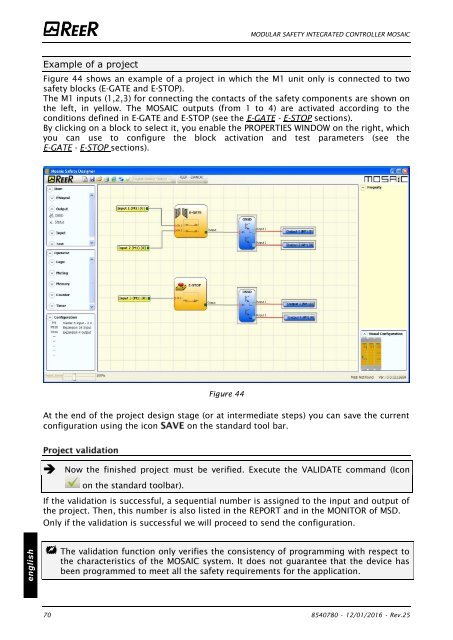
Figure 44 shows an example of a project in which the M1 unit only is connected to two<br />
safety blocks (E-GATE and E-STOP).<br />
The M1 inputs (1,2,3) for connecting the contacts of the safety components are shown on<br />
the left, in yellow. The MOSAIC outputs (from 1 to 4) are activated according to the<br />
conditions defined in E-GATE and E-STOP (see the E-GATE - E-STOP sections).<br />
By clicking on a block to select it, you enable the PROPERTIES WINDOW on the right, which<br />
you can use to configure the block activation and test parameters (see the<br />
E-GATE - E-STOP sections).<br />
Figure 44<br />
At the end of the project design stage (or at intermediate steps) you can save the current<br />
configuration using the icon on the standard tool bar.<br />
Now the finished project must be verified. Execute the VALIDATE command (Icon<br />
on the standard toolbar).<br />
If the validation is successful, a sequential number is assigned to the input and output of<br />
the project. Then, this number is also listed in the REPORT and in the MONITOR of MSD.<br />
Only if the validation is successful we will proceed to send the configuration.<br />
english<br />
The validation function only verifies the consistency of programming with respect to<br />
the characteristics of the MOSAIC system. It does not guarantee that the device has<br />
been programmed to meet all the safety requirements for the application.<br />
70 8540780 • 12/01/2016 • Rev.25


![BRESIMAR(asaTek)-Beckhoff-Livro Formação Técnica TwinCAT 2-v1.2_2009 [pt]](https://img.yumpu.com/62853104/1/190x245/bresimarasatek-beckhoff-livro-formacao-tecnica-twincat-2-v12-2009-pt.jpg?quality=85)