REER-Mosaic Manual
MOSAIC - Installation and use manual
MOSAIC - Installation and use manual

You also want an ePaper? Increase the reach of your titles
YUMPU automatically turns print PDFs into web optimized ePapers that Google loves.
MODULAR SAFETY INTEGRATED CONTROLLER MOSAIC<br />
t = 250ms<br />
250ms < t1< 5s<br />
t2 = 250ms<br />
SAFETY RELAYS (MR2, MR4, MOR4, MOR4S8)<br />
Characteristics of the output circuit.<br />
The MR2/MR4 units use guided contact safety relays, each of which provides<br />
.<br />
The MR2 unit uses two safety relays and the MR4 uses four.<br />
The MOR4/MOR4S8 units use four guided-contact safety relays. Each relay provides one<br />
NO contact monitored by the module logic through internal FBK contact.<br />
Refer to the "RELAY" section to check the possible MOR4/MOR4S8 operation modes<br />
configurable with MSD software.<br />
Excitation voltage<br />
Minimum switchable voltage<br />
Minimum switchable current<br />
Maximum switchable voltage (DC)<br />
Maximum switchable voltage (AC)<br />
Maximum switchable current<br />
Response time<br />
Mechanical life of contacts<br />
Table 18<br />
To guarantee correct isolation and avoid the risk of premature ageing of or damage<br />
to the relays, each output line must be protected using a fast acting 4A fuse and the<br />
load characteristics must be consistent with those specified in Table 12.<br />
See the "MR2/MR4" section (for further details on these relays).<br />
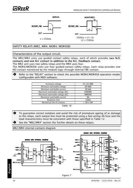
MR2/MR4 internal contacts diagram<br />
English<br />
Figure 7<br />
30 8540780 • 12/01/2016 • Rev.25


![BRESIMAR(asaTek)-Beckhoff-Livro Formação Técnica TwinCAT 2-v1.2_2009 [pt]](https://img.yumpu.com/62853104/1/190x245/bresimarasatek-beckhoff-livro-formacao-tecnica-twincat-2-v12-2009-pt.jpg?quality=85)