REER-Mosaic Manual
MOSAIC - Installation and use manual
MOSAIC - Installation and use manual

Create successful ePaper yourself
Turn your PDF publications into a flip-book with our unique Google optimized e-Paper software.
MODULAR SAFETY INTEGRATED CONTROLLER MOSAIC<br />
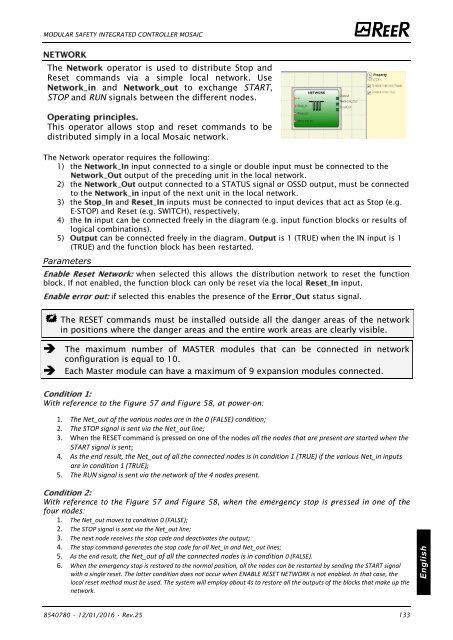
The<br />
operator is used to distribute Stop and<br />
Reset commands via a simple local network. Use<br />
and<br />
to exchange START,<br />
STOP and RUN signals between the different nodes.<br />
This operator allows stop and reset commands to be<br />
distributed simply in a local <strong>Mosaic</strong> network.<br />
The Network operator requires the following:<br />
1) the input connected to a single or double input must be connected to the<br />
output of the preceding unit in the local network.<br />
2) the output connected to a STATUS signal or OSSD output, must be connected<br />
to the<br />
input of the next unit in the local network.<br />
3) the and inputs must be connected to input devices that act as Stop (e.g.<br />
E-STOP) and Reset (e.g. SWITCH), respectively.<br />
4) the input can be connected freely in the diagram (e.g. input function blocks or results of<br />
logical combinations).<br />
5) can be connected freely in the diagram. is 1 (TRUE) when the IN input is 1<br />
(TRUE) and the function block has been restarted.<br />
Parameters<br />
when selected this allows the distribution network to reset the function<br />
block. If not enabled, the function block can only be reset via the local<br />
input.<br />
if selected this enables the presence of the<br />
status signal.<br />
The RESET commands must be installed outside all the danger areas of the network<br />
in positions where the danger areas and the entire work areas are clearly visible.<br />
The maximum number of MASTER modules that can be connected in network<br />
configuration is equal to 10.<br />
Each Master module can have a maximum of 9 expansion modules connected.<br />
With reference to the Figure 57 and Figure 58, at power-on:<br />
1. The Net_out of the various nodes are in the 0 (FALSE) condition;<br />
2. The STOP signal is sent via the Net_out line;<br />
3. When the RESET command is pressed on one of the nodes all the nodes that are present are started when the<br />
START signal is sent;<br />
4. As the end result, the Net_out of all the connected nodes is in condition 1 (TRUE) if the various Net_in inputs<br />
are in condition 1 (TRUE);<br />
5. The RUN signal is sent via the network of the 4 nodes present.<br />
With reference to the Figure 57 and Figure 58, when the emergency stop is pressed in one of the<br />
four nodes:<br />
1. The Net_out moves to condition 0 (FALSE);<br />
2. The STOP signal is sent via the Net_out line;<br />
3. The next node receives the stop code and deactivates the output;<br />
4. The stop command generates the stop code for all Net_in and Net_out lines;<br />
5. As the end result, the Net_out of all the connected nodes is in condition 0 (FALSE).<br />
6. When the emergency stop is restored to the normal position, all the nodes can be restarted by sending the START signal<br />
with a single reset. The latter condition does not occur when ENABLE RESET NETWORK is not enabled. In that case, the<br />
local reset method must be used. The system will employ about 4s to restore all the outputs of the blocks that make up the<br />
network.<br />
English<br />
8540780 • 12/01/2016 • Rev.25 133


![BRESIMAR(asaTek)-Beckhoff-Livro Formação Técnica TwinCAT 2-v1.2_2009 [pt]](https://img.yumpu.com/62853104/1/190x245/bresimarasatek-beckhoff-livro-formacao-tecnica-twincat-2-v12-2009-pt.jpg?quality=85)