KVPT’s Patan Darbar Earthquake Response Campaign - Work to Date - September 2016

Create successful ePaper yourself
Turn your PDF publications into a flip-book with our unique Google optimized e-Paper software.
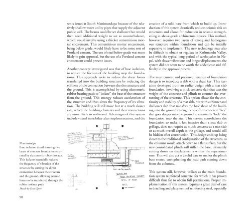
Manimandpa<br />
Base isolation detail showing two<br />
layers of concrete foundation separated<br />
by elas<strong>to</strong>meric rubber isola<strong>to</strong>r.<br />
This isola<strong>to</strong>r essentially reduces<br />
the frequency of vibration of the<br />
structure by cutting the direct<br />
connection between the structure<br />
and the ground, allowing seismic<br />
forces <strong>to</strong> be transferred through the<br />
rubber isola<strong>to</strong>r pads.<br />
Sketch by Evan Speer<br />
sents issues at South Manimandapa because of the relatively<br />
shallow water utility pipes that supply the adjacent<br />
public well. The beams could be set shallower but would<br />
then need additional weight <strong>to</strong> act as counterbalance,<br />
which would involve using a thicker cementitious mortar<br />
encasement. This cementitious mortar encasement,<br />
being below grade, would likely have <strong>to</strong> be some sort of<br />
Portland cement. The use of steel below grade was more<br />
likely <strong>to</strong> gain approval, but the use of a Portland cement<br />
encasement could present issues.<br />
Another concept investigated was that of base isolation,<br />
<strong>to</strong> reduce the friction of the building a<strong>to</strong>p the foundations.<br />
This approach seeks <strong>to</strong> reduce the shear forces<br />
transferred in<strong>to</strong> the building structure by reducing the<br />
stiffness of the connection between the the structure and<br />
the ground. This is accomplished by using elas<strong>to</strong>meric<br />
rubber bearing pads <strong>to</strong> “isolate” the base of the structure<br />
from the ground. This strategy reduces acceleration of<br />
the structure and thus slows the frequency of its vibration.<br />
The building will still move but at a much slower<br />
rate, which the building elements and their connections<br />
are more likely <strong>to</strong> withstand. Advantages of this system<br />
include virtual invisibility after implementation, and the<br />
creation of a solid base from which <strong>to</strong> build up. Introduction<br />
of this system drastically reduces seismic risk on<br />
structures and allows for reduction in seismic strengthening<br />
in above-grade architectural spaces. This method,<br />
however, requires two layers of strong and homogeneous<br />
structure within foundation and can be initially<br />
expensive <strong>to</strong> implement. The new technology may also<br />
be difficult <strong>to</strong> obtain or regulate in Kathmandu Valley,<br />
and with the typical long-period of earthquakes in Nepal,<br />
with slower vibrations and longer displacements, the<br />
system did not seem <strong>to</strong> be worth the added cost and difficulty<br />
in the approval process.<br />
The most current and preferred iteration of foundation<br />
design is <strong>to</strong> introduce a slab with a shear key. This iteration<br />
developed from an earlier design with a mat slab<br />
foundation, involving a thick concrete slab that uses the<br />
weight of the concrete and plinth <strong>to</strong> counter the overturning<br />
of the structure. This option allows for the continuity<br />
and stability of a mat slab, but with a thinner and<br />
shallower slab that transfers the base shear of the building<br />
in<strong>to</strong> the ground through a cruciform concrete “key”<br />
that goes deeper in<strong>to</strong> the ground <strong>to</strong> essentially “lock” the<br />
foundation in<strong>to</strong> the site. This system consolidates the<br />
foundation <strong>to</strong> make it less invasive than a mat slab or<br />
grillage, does not require as much concrete as a mat slab<br />
or as much overall depth as the grillage, and would still<br />
be hidden after construction. This design ends up being<br />
closer <strong>to</strong> the traditional configuration of the structure, as<br />
the columns would attach down <strong>to</strong> a flat surface, but the<br />
new consolidated plinth will stiffen the base, ultimately<br />
cutting down on displacements within the superstructure.<br />
This will also act as a solid base <strong>to</strong> anchor the plinth<br />
base s<strong>to</strong>nes, strengthening the load path coming down<br />
from the columns.<br />
This system still, however, utilizes as the main foundation<br />
system reinforced concrete, for which it has proven<br />
difficult thus far <strong>to</strong> obtain full permissions. Proper implementation<br />
of this system requires a great deal of care<br />
in detailing and placement of reinforcing steel, especially<br />
90