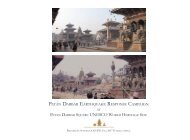
KVPT’s Patan Darbar Earthquake Response Campaign - Work to Date - September 2016

You also want an ePaper? Increase the reach of your titles
YUMPU automatically turns print PDFs into web optimized ePapers that Google loves.
aside for aesthetic reasons and because the introduction<br />
of a new structure woven through the traditional framework<br />
of the building would limit access <strong>to</strong> the central<br />
core and throughout the structure.<br />
Option 3<br />
This option investigated joining sound existing timber<br />
with new timber at its rotten base, and encase the timber<br />
columns with hollow steel section from just above the<br />
resulting timber joint down <strong>to</strong> a slab or grillage foundation.<br />
The structure above the ground floor arcade would<br />
then be reinforced with timber beams and steel collars<br />
at the intersections of the central core columns. Small<br />
solid steel tension rods would then act as cross bracing at<br />
the ground floor <strong>to</strong> connect the steel reinforcing on central<br />
core columns. This option would result in the potential<br />
<strong>to</strong> keep the his<strong>to</strong>ric timbers in the structure, and<br />
the visibility of these timbers would not be inhibited.<br />
There would, however, be steel tension rods installed <strong>to</strong><br />
provide a secondary load path for lateral loads that pull<br />
against the building, allowing these loads <strong>to</strong> be pulled<br />
back down in<strong>to</strong> the foundation.Visibility through the<br />
timber arcade would be slightly disrupted by the cross<br />
bracing, and access <strong>to</strong> the central core of the structure<br />
would be impeded. This option would not be viable at<br />
the Manimandapa North, because the central core of<br />
the structure is used for religious puja. Additionally, the<br />
his<strong>to</strong>ric timber elements would still be used for gravity<br />
loads, so it would be a composite system whose connections<br />
and geometry of cross bracing would be more<br />
difficult <strong>to</strong> determine and implement. The complexity,<br />
difficulty of implementation, and visibility of this system<br />
rendered it nonviable for the current situation.<br />
Option 4<br />
A later option involved joining sound existing timber<br />
with new timber at column bases, encased with a fitted<br />
steel shoe that slides on<strong>to</strong> the base of the timber column.<br />
This shoe would be either embedded in<strong>to</strong> a slab or bolted/welded<br />
<strong>to</strong> a grillage foundation, and would allow for<br />
embedded dowels <strong>to</strong> secure the timber column. Ensuring<br />
that the shoe fully covers the timber joint, the wood<br />
would be routed at the edges <strong>to</strong> leave the timber column<br />
and the steel faces flush. The columns would then also<br />
be connected <strong>to</strong> a grid of horizontal timber beams just<br />
above the open arcade <strong>to</strong> stiffen them by shortening the<br />
span. The intersections of these beams would be reinforced<br />
with steel angles, and dowels would pin the columns<br />
at this point. This way, the main architectural feel<br />
and appearance remain intact, wood joinery and base<br />
connection are strengthened against lateral loads, and<br />
we are able <strong>to</strong> keep the his<strong>to</strong>ric timbers in the structure.<br />
This allows for a flexible system, utilizing mainly timber<br />
framing in the upper structure, with reinforced connections<br />
and a stable foundation <strong>to</strong> limit vibrations. This<br />
option would be a compromise structurally, but would<br />
still be a significant improvement in safety and stability<br />
over the original construction.<br />
The design compromise that was chosen evolved from<br />
Option 4 as described above. With a base foundation<br />
utilizing a reinforced concrete slab with cruciform shear<br />
key as its base, this would aid in the establishment of a<br />
damp proof course. The columns and base s<strong>to</strong>nes would<br />
have direct positive structural connections down <strong>to</strong> this<br />
concealed concrete slab. This would provide resistance<br />
against the pullout seen at these connections during the<br />
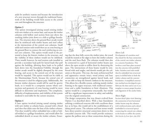
Above Left<br />
Development of a stainless steel<br />
shoe detail for the base connection<br />
of the central core timber columns<br />
<strong>to</strong> a concrete foundation. This<br />
involves a steel base plate recessed<br />
in<strong>to</strong> the concrete with predrilled<br />
holes. Stainless steel rods would<br />
then be embedded in<strong>to</strong> structural<br />
epoxy in drilled holes in both the<br />
timber column and the concrete<br />
foundation. A simplified construction<br />
method was developed <strong>to</strong> prefabricate<br />
the shoe and <strong>to</strong> use it as a<br />
template <strong>to</strong> ensure proper location<br />
and alignment of the anchor holes.<br />
Above Right<br />
Section detail (plan view) showing<br />
the connection of new horizontal<br />
timber beams a<strong>to</strong>p the columns<br />
with reinforced joints and a dowel<br />
(embedded in structural epoxy)<br />
connecting the central core column<br />
<strong>to</strong> the beams <strong>to</strong> stiffen the system.<br />
Both sketches by Evan Speer, July <strong>2016</strong><br />
93