

UWE Bristol Engineering showcase 2015

Create successful ePaper yourself
Turn your PDF publications into a flip-book with our unique Google optimized e-Paper software.
Adam Caldwell<br />
BEng (Hons) Mechanical <strong>Engineering</strong><br />
Project Supervisor<br />
Dr. David Richardson<br />
The Structural Optimisation of Carbon Fibre Composites and Interfaces<br />
Introduction<br />
Hollow tubular composites can be found<br />
across a wide array of sporting<br />
applications. The most prominent example<br />
of this manufacture can be seen in the<br />
mass production of carbon fibre road bike<br />
frames for both professional cyclists and<br />
fans alike. Although an expensive<br />
alternative to its metallic counterpart,<br />
composites offer superior strength and<br />
stiffness capabilities. These factors,<br />
twinned with the component being very<br />
low in weight, make the use of composites<br />
a tantalising proposition for designers and<br />
engineers.<br />
In this investigation<br />
multiple T-section<br />
handlebar<br />
components<br />
(example shown in<br />
Figure 1) and<br />
footplate prototypes<br />
have been produced<br />
using bladder<br />
inflation moulding<br />
(BIM). Having<br />
developed the<br />
design of the<br />
footplate a wet<br />
layup vacuum<br />
technique was then<br />
also employed.<br />
Figure 1 – Carbon,<br />
Aluminum & Steel<br />
handlebars<br />
Handlebar Manufacture & Testing<br />
A total of six handlebars were produced over<br />
the course of the project, with three of<br />
those being used for testing. The ply<br />
orientation and material layup were driven<br />
by the differing forces acting on various<br />
areas of the component (bars, T-Section and<br />
stem) during use. Following completion of the layup<br />
the part was left to cure for 2 hours at a temperature<br />
of 180°C . One bend test (see Fig 2a and 2b) and two<br />
compression tests served to inform future<br />
production and anaylsed each of the components<br />
mechanical capability compared to calculated values<br />
for maximum stress and deflection.<br />
Figure 2a & 2b – Stem bend test setup on Instron 4204<br />
Various issues were encountered and overcome<br />
during manufacturing e.g. material pinching within<br />
tool, air leakages. Testing on the fourth handlebar<br />
showed each of the bars themselves could<br />
withstand a maximum force of 924.5N, equating to a<br />
weight of approximately 94kg per bar.<br />
Finite Element Analysis (FEA)<br />
Using Abaqus/CAE software regions of the handlebar<br />
were modelled to investigate areas of high stress<br />
concentration and measure deflective behaviour (Fig<br />
3). These values were then validated against<br />
Figure 3 – Stress Contour Plot from LH handlebar in Torsion<br />
theoretical calculations and studied alongside the<br />
testing data. Through collation of this information it<br />
was then possible to optimise the design of the<br />
component and ensure maximum performance.<br />
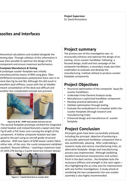
Footplate Manufacture & Testing<br />
A prototype scooter footplate was initially<br />
manufactured by means of BIM using glass fibre<br />
(GFRP)and incorporated a polystyrene foam core in its<br />
neck (See Fig 3a and 3b). Although this did result in<br />
excellent axial stiffness, issues with the air bladder<br />
meant consolidation of the deck was difficult and<br />
another less complicated concept was pursued.<br />
Figure 3a & 3b – GFRP neck section and core cut out<br />
The second footplate prototype omitted the integrated<br />
metal headset and instead featured a swept neck (See<br />
Fig 4) with a PVC foam core running the length of the<br />
component. A hollow composite headset was later<br />
glued to the part using an aircraft grade structural<br />
adhesive. With two layers of 0/90 weave carbon fabric<br />
either side of the core, the cured component exhibited<br />
excellent flexural stiffness – reaching a maximum load<br />
of 1429.27N during a 3-point bend test (shown below).<br />
Figure 4 – 3-point bend test on scooter deck<br />
Project summary<br />
The primary aim of this investigation was to<br />
structurally enhance and optimise the design of an<br />
existing micro scooter handlebar. Following a<br />
focused design, build and test campaign of the<br />
composite handlebars, a secondary study was then<br />
undertaken to evaluate and develop the<br />
manufacturing method utilised to produce scooter<br />
footplate components.<br />
Project Objectives<br />
• Structural optimisation of the composite layup for<br />
scooter handlebars.<br />
• Undertake Finite Element Analysis study<br />
• Manufacture a optimised handlebar component<br />
• Develop practical laboratory skill<br />
• Validate optimisation through testing<br />
• Evaluate the embodiment of a headset within the<br />
scooter footplate (through research and<br />
manufacturing trials)<br />
• Enhanced design and manufacture of scooter<br />
footplate<br />
Project Conclusion<br />
All project goals have been successfully achieved,<br />
including the principal objective of producing a<br />
structurally optimised handlebar component that is<br />
also aesthetically pleasing. After undertaking a<br />
research study and various manufacturing trials, an<br />
alternative footplate design and manufacturing<br />
process was implemented. Although exhibiting<br />
excellent mechanical characteristics and surface<br />
finish in the deck section , the footplate lacks the<br />
necessary stiffness and strength in the neck region –<br />
thus highlighting this as a key area for improvement<br />
with any further investigations. A study aimed at<br />
combining the two components into one scooter<br />
assembly is also highly recommended.