

UWE Bristol Engineering showcase 2015

You also want an ePaper? Increase the reach of your titles
YUMPU automatically turns print PDFs into web optimized ePapers that Google loves.
Samuel Hill<br />
Meng Part A Aerospace Design <strong>Engineering</strong><br />
Project Supervisor<br />
Dr. Oluwamayokun B. Adetoro<br />
Ph.D. Meng MRAeS<br />
Design and Numerical Analysis of a Scramjet Inlet<br />
This project is an investigation into Scramjet design and analysis with potential to expand the design to accommodate ramjet/scramjet<br />
transition at Mach 6. The literary review consisted of investigation into the application of scramjets, potential problems encountered<br />
while travelling at hypersonic speeds and possible design solutions. In order to validate the use of computational fluid dynamics wind<br />
tunnel testing ensued. The tunnel was modelled using the computational software ANSYS Fluent and comparison was made to real<br />
practical test results. Once this was completed the inlet was designed based on the ‘shock on lip’ criterion and oblique shock charts and<br />
equations were used to find the optimum geometry. This geometry was then analysed using ANSYS Fluent and the performance was<br />
evaluated.<br />
Computational Validation<br />
The supersonic wind tunnel in the universities fluid dynamics laboratory was<br />
analysed numerically in order to validate the use of computational software.<br />
The picture to the left represents the distribution of static temperature along<br />
the wind tunnel constructed through computational analysis. The results of<br />
which are very comparable to that of practical tests.<br />
Initial Design<br />
Hypersonic vehicle inlets harness the kinetic energy of the incoming air to<br />
generate shock waves the compress to oncoming air to a desired value<br />
perfect for combustion to take place. The design constructed for analysis was<br />
created by the use of the oblique shock relations. The equations which<br />
describe such will predict the aerodynamic characteristics succeeding a shock<br />
wave. These equations are used to predict the geometry which would create<br />
optimum conditions leaving the inlet.. This geometry is constructed through<br />
the use of CAD software SolidWorks and is shown to the left. The Inlet will be<br />
situated on the abdomen of the vehicle body to allow integration into a<br />
waverider vehicle design.<br />
Project summary<br />
This study will focus on the modelling and the design<br />
of the inlet section or isolator section whilst<br />
considering different flow conditions and operating<br />
conditions. This will predominantly be conducted<br />
using computational fluid dynamic (CFD) simulations,<br />
whist demonstrating the use of appropriate CFD<br />
solver, accurate modelling and appropriate<br />
assumption made; hence the results must be well<br />
validated.<br />
Project Objectives<br />
The desired output of this project will be validation of<br />
use of numerical techniques as well as an inlet design<br />
from which future research can benefit from. If a<br />
company would wish to construct a hypersonic<br />
vehicle with this mission profile this project may be<br />
useful.<br />
Project Conclusion<br />
This project has validated the authors use of<br />
Computational Fluid Dynamic Software. Secondly the<br />
use of oblique shock equations and charts are<br />
adequate for the construction of simple hypersonic<br />
inlet designs. The software ANSYS Fluent is capable of<br />
modelling the complex aerodynamics of hypersonic<br />
air intake as proven in the comparison section of this<br />
study, in which numerically generated results are<br />
compared to those calculated theoretical y.<br />
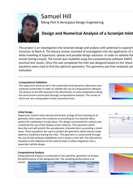
Computational Analysis<br />
Computational analysis is conducted on the specified geometry to analyse<br />
the performance of the designed inlet. The resulting performance is as<br />
shown:<br />
Theoretical CFD Run 1 CFD Run2<br />
Total Pressure Ratio 0.941187877 0.941942284 0.949762764<br />
Adiabatic Compression<br />
Efficiency<br />
0.672166124 0.708740605 0.741988651<br />
Kinetic Energy Efficiency 0.983289033 0.983306693 0.987638376