

UWE Bristol Engineering showcase 2015

Create successful ePaper yourself
Turn your PDF publications into a flip-book with our unique Google optimized e-Paper software.
Christopher Farndon<br />
BEng Aerospace Design <strong>Engineering</strong><br />
Project Supervisor<br />
Dr. Chris Toomer<br />
Investigation, creation and validation of an inverse design code for twodimensional<br />
aerofoils using MATLAB<br />
Creation of MATLAB model<br />
After completing a thorough literature<br />
survey, it was decided that the most suitable<br />
method of inverse design for this project was<br />
the Modified Garabedian McFadden (MGM)<br />
method. This approach uses coefficient of<br />
pressure distributions to compute a residual<br />
value between a target and initial Cp<br />
distribution, with this driving an iteration<br />
process which optimises an initial aerofoil<br />
shape. The fundamental equation used to<br />
compute the aerofoil change is:<br />
AA δδδδ + BB ∂∂(δδδδ)<br />
∂∂∂∂<br />
− CC ∂∂2 δδδδ<br />
∂∂xx 2<br />
= CCCC tttttttttttt − CCCC iiiiiiiiiiiiii<br />
This second order ordinary differential<br />
equation can be solved using a central finite<br />
difference method for δδδδ (the change in<br />
aerofoil height) which can then be added to<br />
the initial aerofoil to create a new shape<br />
closer to the required aerofoil. This process<br />
is repeated in an iterative loop until the Cp<br />
residual is reduced to 0 (or a negligible value)<br />
indicating the aerofoil has been optimised<br />
correctly.<br />
Tri-diagonal sparse matrix created to solve the fundamental equation<br />
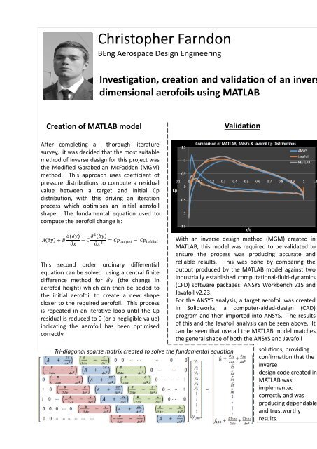
Validation<br />
With an inverse design method (MGM) created in<br />
MATLAB, this model was required to be validated to<br />
ensure the process was producing accurate and<br />
reliable results. This was done by comparing the<br />
output produced by the MATLAB model against two<br />
industrially established computational-fluid-dynamics<br />
(CFD) software packages: ANSYS Workbench v15 and<br />
Javafoil v2.23.<br />
For the ANSYS analysis, a target aerofoil was created<br />
in Solidworks, a computer-aided-design (CAD)<br />
program and then imported into ANSYS. The results<br />
of this and the Javafoil analysis can be seen above. It<br />
can be seen that overall the MATLAB model matches<br />
the general shape of both the ANSYS and Javafoil<br />
solutions, providing<br />
confirmation that the<br />
inverse<br />
design code created in<br />
MATLAB was<br />
implemented<br />
correctly and was<br />
producing dependable<br />
and trustworthy<br />
results.<br />
Testing<br />
The testing phase allowed the capabilities of the<br />
developed MATLAB inverse design code to be<br />
investigated. A variety of test series were<br />
created; each assessing a different aspect of the<br />
program’s functionality. The constants A, B and<br />
C seen in the fundamental equation were<br />
required to be determined experimentally, as<br />
well as the optimal value of the Cp error. Once<br />
these were determined, various tests were<br />
performed to observe the MATLAB’s success at<br />
transforming an initial aerofoil shape based on a<br />
variety of key aerofoil design parameters:<br />
camber, maximum thickness and the position of<br />
the maximum thickness.<br />
These tests were all passed with overwhelming<br />
success, with the inverse design code efficiently<br />
optimising the aerofoil shape to within an<br />
acceptable level of accuracy for any change in<br />
design criteria.<br />
The testing phase continued on to assess the<br />
MATLAB model’s ability to analyse viscous flows,<br />
where it also successfully passed this, increasing<br />
the flexibility and usefulness of the algorithm.<br />
3D representation of change in aerofoil shape over time.<br />
Project summary<br />
The project attempted to gain an<br />
understanding of inverse design methods<br />
when applied to the aerospace industry, by<br />
creating, validating and testing a working<br />
model from first-principles.<br />
Project Objectives<br />
Overall project objectives:<br />
• Create an inverse design code in MATLAB.<br />
• Use computational-fluid-dynamics (CFD)<br />
to validate the output of the inverse<br />
design code .<br />
• Devise and complete a comprehensive set<br />
of test procedures to investigate the<br />
program’s ability to successfully optimise<br />
an aerofoil based on a variety of varying<br />
design criteria.<br />
Project Conclusion<br />
An inverse design code was successfully<br />
created in MATLAB, before being validated<br />
and tested to confirm the program produced<br />
accurate and reliable aerofoil shapes. The<br />
developed program provided not only a<br />
useful aerodynamic design tool, but also<br />
served as an opportunity to observe the<br />
concepts and principles associated with<br />
inverse design first hand by creating a<br />
working model first-hand.