

ssw03_plus_series

Create successful ePaper yourself
Turn your PDF publications into a flip-book with our unique Google optimized e-Paper software.
3<br />
INSTALLATION<br />
The line voltage must be compatible with the rated voltage<br />
of the Soft-Starter.<br />
For installation use the cable cross sections and the fuses<br />
recommended in Table 3.1, 3.2, 3.3, 3.4. Maximum torque as<br />
indicated in table 3.5.<br />
Power factor correction capacitors must never be installed<br />
on the Soft-Starter output.<br />
The Soft-Starters must be grounded. For this purpose use a<br />
cable with a cross section as indicated in Tables 3.2, 3.3, 3.4.<br />
Connect it to a specific grounding bar or to the general<br />
grounding point (resistance 10 ohms).<br />
Do not share the grounding wiring with other equipment<br />
which operate at high currents (for instance, high voltage<br />
motors, welding machines, etc.).<br />
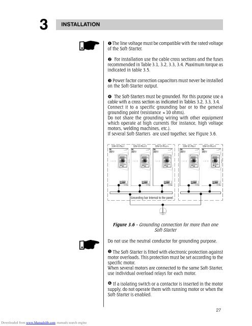
If several Soft-Starters are used together, see Figure 3.6.<br />
SSW-03 Plus I SSW-03 Plus II SSW-03 Plus n<br />
SSW-03 Plus I<br />
SSW-03 Plus II<br />
Grounding bar Internal to the panel<br />
Figure 3.6 - Grounding connection for more than one<br />
Soft-Starter<br />
Do not use the neutral conductor for grounding purpose.<br />
The Soft-Starter is fitted with electronic protection against<br />
motor overloads. This protection must be set according to the<br />
specific motor.<br />
When several motors are connected to the same Soft-Starter,<br />
use individual overload relays for each motor.<br />
If a isolating switch or a contactor is inserted in the motor<br />
supply, do not operate them with running motor or when the<br />
Soft-Starter is enabled.<br />
27<br />
Downloaded from www.Manualslib.com manuals search engine