

ssw03_plus_series

You also want an ePaper? Increase the reach of your titles
YUMPU automatically turns print PDFs into web optimized ePapers that Google loves.
6<br />
DETAILED PARAMETER DESCRIPTION<br />
2) Within the motor delta connection<br />
of the switch = 120A<br />
of the motor = 140A<br />
1.4 x 140A = 196A<br />
of the switch within delta<br />
120A x 1.73 = 207.8A<br />
196A<br />
delta switch<br />
= 196A<br />
207.8A =<br />
0.94 x switch<br />
P12 = 94% of of delta switch = 140% of the motor.<br />
6.3.8 - P14-<br />
Immediate<br />
undercurrent<br />
(%IN of the<br />
switch)<br />
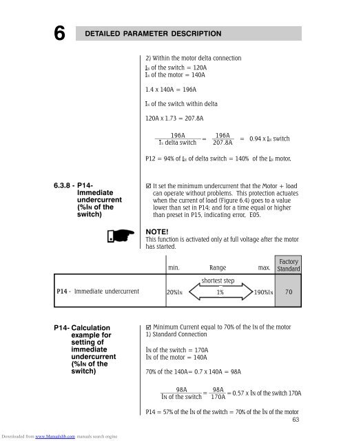
It set the minimum undercurrent that the Motor + load<br />
can operate without problems. This protection actuates<br />
when the current of load (Figure 6.4) goes to a value<br />
lower than set in P14; and for a time equal or higher<br />
than preset in P15, indicating error, E05.<br />
NOTE!<br />
This function is activated only at full voltage after the motor<br />
has started.<br />
P14 - Immediate undercurrent<br />
min. Range max.<br />
shortest step<br />
20%IN 1% 190%IN<br />
Factory<br />
Standard<br />
70<br />
P14- Calculation<br />
example for<br />
setting of<br />
immediate<br />
undercurrent<br />
(%IN of the<br />
switch)<br />
Minimum Current equal to 70% of the IN of the motor<br />
1) Standard Connection<br />
IN of the switch = 170A<br />
IN of the motor = 140A<br />
70% of the 140A= 0.7 x 140A = 98A<br />
98A<br />
=<br />
IN of the switch<br />
98A<br />
= 0.57 x IN of the switch 170A<br />
170A<br />
P14 = 57% of the IN of the switch = 70% of the IN of the motor<br />
63<br />
Downloaded from www.Manualslib.com manuals search engine