Grundlagen der Digitaltechnik - Ing. H. Heuermann - FH Aachen
Grundlagen der Digitaltechnik - Ing. H. Heuermann - FH Aachen
Grundlagen der Digitaltechnik - Ing. H. Heuermann - FH Aachen

Sie wollen auch ein ePaper? Erhöhen Sie die Reichweite Ihrer Titel.
YUMPU macht aus Druck-PDFs automatisch weboptimierte ePaper, die Google liebt.
110 Highspeed-Datentransfer<br />
NB7L86M<br />
VTD0 D0 D0 VTD0<br />
16 15 14 13<br />
Exposed Pad (EP)<br />
V CC<br />
1<br />
12<br />
V EE<br />
SEL<br />
SEL<br />
2<br />
3<br />
NB7L86M<br />
11<br />
10<br />
Q<br />
Q<br />
VTSEL<br />
4<br />
9<br />
V CC<br />
5 6 7 8<br />
VTD1 D1 D1 VTD1<br />
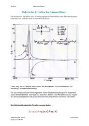
Figure 2. Pin Configuration (Top View)<br />
Table 1. PIN DESCRIPTION<br />
Pin Name I/O Description<br />
1, 9 V CC Power Supply Positive supply voltage. All V CC pins must be externally connected to power<br />
supply to guarantee proper operation.<br />
2 SEL LVPECL, CML, LVCMOS,<br />
LVTTL, LVDS Input<br />
3 SEL LVPECL, CML, LVCMOS,<br />
LVTTL, LVDS Input<br />
Inverted differential select logic input.<br />
Non inverted differential select logic Input.<br />
4 V TSEL Common internal 50 termination pin for SEL/SEL. See Table 6. (Note 1)<br />
5 V TD1 Internal 50 termination pin for D1. See Table 6. (Note 1)<br />
6 D1 LVPECL, CML, LVCMOS,<br />
LVTTL, LVDS Input<br />
7 D1 LVPECL, CML, LVCMOS,<br />
LVTTL, LVDS Input<br />
Non inverted differential clock/data input D1. (Note 1)<br />
Inverted differential clock/data input D1. (Note 1)<br />
8 V TD1 Internal 50 termination pin for D1. See Table 6. (Note 1)<br />
10 Q CML Output Non inverted output with internal 50 source termination resistor. (Note 2)<br />
11 Q CML Output Inverted output with internal 50 source termination resistor. (Note 2)<br />
12 V EE Power Supply Negative supply voltage. All V EE pins must be externally connected to power<br />
supply to guarantee proper operation.<br />
13 V TD0 Internal 50 termination pin for D0. (Note 1)<br />
14 D0 LVPECL, CML, LVCMOS,<br />
LVTTL, LVDS Input<br />
15 D0 LVPECL, CML, LVCMOS,<br />
LVTTL, LVDS Input<br />
Non inverted differential clock/data input D0. (Note 1)<br />
Non inverted differential clock/data input D0. (Note 1)<br />
16 V TD0 Internal 50 termination pin for D0. (Note 1)<br />
EP<br />
Exposed Pad. Thermal pad on the package bottom must be attached to a<br />
heatsinking conduit to improve heat transfer. It is recommended to connect the EP<br />
to the lower potential (V EE ).<br />
1. In the differential configuration when the input termination pins (V TDx , V TDx , V TSEL ) are connected to a common termination voltage or left<br />
open, and if no signal is applied on Dx, Dx, SEL and SEL then the device will be susceptible to self oscillation.<br />
2. CML output require 50 receiver termination resistor to VCC for proper operation.