- Page 1 and 2:
FUNDAMENTALS OF ENGINEERING SUPPLIE
- Page 3 and 4:
Published by the National Council o
- Page 5 and 6:
CONTENTS Units.....................
- Page 7 and 8:
CONVERSION FACTORS Multiply By To O
- Page 9 and 10:
Case 4. Circle e = 0: (x - h) 2 + (
- Page 11 and 12:
MATRICES A matrix is an ordered rec
- Page 13 and 14:
Taylor's Series f ( x) = f ( a) ( a
- Page 15 and 16:
MENSURATION OF AREAS AND VOLUMES No
- Page 17 and 18:
CENTROIDS AND MOMENTS OF INERTIA Th
- Page 19 and 20:
Numerical Integration Three of the
- Page 21 and 22:
PROBABILITY FUNCTIONS A random vari
- Page 23 and 24:
HYPOTHESIS TESTING Consider an unkn
- Page 25 and 26:
ENGINEERING PROBABILITY AND STATIST
- Page 27 and 28:
22 CRITICAL VALUES OF THE F DISTRIB
- Page 29 and 30:
FORCE A force is a vector quantity.
- Page 31 and 32:
26 y y y y y y C Figure Area & Cent
- Page 33 and 34:
28 y y y Figure Area & Centroid Are
- Page 35 and 36:
Normal and Tangential Components y
- Page 37 and 38:
M is the moment applied to the part
- Page 39 and 40:
The figure shows a fourbar slider-c
- Page 41 and 42:
It may also be shown that the undam
- Page 43 and 44:
UNIAXIAL STRESS-STRAIN Stress-Strai
- Page 45 and 46:
STATIC LOADING FAILURE THEORIES Bri
- Page 47 and 48:
Using the stress-strain relationshi
- Page 49 and 50:
DENSITY, SPECIFIC VOLUME, SPECIFIC
- Page 51 and 52:
The Field Equation is derived when
- Page 53 and 54:
Specific fittings have characterist
- Page 55 and 56:
FLUID MEASUREMENTS The Pitot Tube -
- Page 57 and 58:
DIMENSIONAL HOMOGENEITY AND DIMENSI
- Page 59 and 60:
MOODY (STANTON) DIAGRAM e, (ft) e,
- Page 61 and 62:
PROPERTIES OF SINGLE-COMPONENT SYST
- Page 63 and 64:
Mixers, Separators, Open or Closed
- Page 65 and 66:
SECOND LAW OF THERMODYNAMICS Therma
- Page 67 and 68:
Temp. o C T 0.01 5 10 15 20 25 30 3
- Page 69 and 70:
P-h DIAGRAM FOR REFRIGERANT HFC-134
- Page 71 and 72:
Gases Substance Air Argon Butane Ca
- Page 73 and 74:
RADIATION The radiation emitted by
- Page 75 and 76:
Use the cylinder diameter in the ev
- Page 77 and 78:
Shape Factor Relations Reciprocity
- Page 79 and 80:
For more information on Biology see
- Page 81 and 82:
Stoichiometry of Selected Biologica
- Page 83 and 84: Avogadro's Number: The number of el
- Page 85 and 86: 80 Specific Example IUPAC Name Comm
- Page 87 and 88: MATERIALS SCIENCE/STRUCTURE OF MATT
- Page 89 and 90: HARDENABILITY Hardenability is the
- Page 91 and 92: POLYMERS Classification of Polymers
- Page 93 and 94: Signal Conditioning Signal conditio
- Page 95 and 96: An alternative form commonly employ
- Page 97 and 98: ENGINEERING ECONOMICS Factor Name C
- Page 99 and 100: ENGINEERING ECONOMICS (continued) 9
- Page 101 and 102: ENGINEERING ECONOMICS (continued) 9
- Page 103 and 104: ENGINEERING ECONOMICS (continued) 9
- Page 105 and 106: B. LICENSEE’S OBLIGATION TO EMPLO
- Page 107 and 108: Common Names and Molecular Formulas
- Page 109 and 110: For mixtures of ideal gases: fi o =
- Page 111 and 112: Distillation Definitions: α = rela
- Page 113 and 114: Cost Segments of Fixed-Capital Inve
- Page 115 and 116: Concentrations of Vaporized Liquids
- Page 117 and 118: COARSE- GRAINED SOILS More than 50%
- Page 119 and 120: STRUCTURAL ANALYSIS Influence Lines
- Page 121 and 122: Pu A's As Mu A's As UNIFIED DESIGN
- Page 123 and 124: SHORT COLUMNS Limits for main reinf
- Page 125 and 126: GRAPH A.15 Column strength interact
- Page 127 and 128: BEAMS: homogeneous beams, flexure a
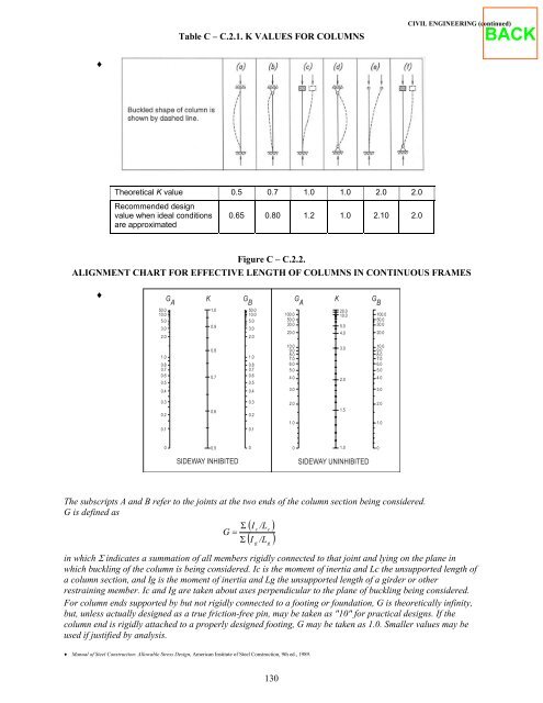
- Page 129 and 130: 124 CIVIL ENGINEERING (continued) B
- Page 131 and 132: 126 CIVIL ENGINEERING (continued) A
- Page 133: Fy = 50 ksi φb = 0.9 φv = 0.9 Sha
- Page 137 and 138: ALLOWABLE STRESS DESIGN SELECTION T
- Page 139 and 140: Kl r ASD Table C-50. Allowable Stre
- Page 141 and 142: Open-Channel Flow Specific Energy 2
- Page 143 and 144: Transportation Models See INDUSTRIA
- Page 145 and 146: VERTICAL CURVE FORMULAS L = Length
- Page 147 and 148: EARTHWORK FORMULAS Average End Area
- Page 149 and 150: , METERS , METERS 144 ENVIRONMENTAL
- Page 151 and 152: Cyclone Cyclone Collection (Particl
- Page 153 and 154: FATE AND TRANSPORT Microbial Kineti
- Page 155 and 156: LANDFILL Break-Through Time for Lea
- Page 157 and 158: 152 ENVIRONMENTAL ENGINEERING (cont
- Page 159 and 160: No. 1 2 3 4 5 6 7 8 9 10 11 12 13 1
- Page 161 and 162: Exposure Residential Exposure Equat
- Page 163 and 164: TOXICOLOGY Dose-Response Curves The
- Page 165 and 166: ♦ Aerobic Digestion Design criter
- Page 167 and 168: where R Cin = stripping factor H′
- Page 169 and 170: Bed Expansion Monosized Multisized
- Page 171 and 172: Stokes' Law V t 2 ( ρp − ρf ) g
- Page 173 and 174: Resistors in Series and Parallel Fo
- Page 175 and 176: RC AND RL TRANSIENTS v R + V 1 −
- Page 177 and 178: AC Machines The synchronous speed n
- Page 179 and 180: LAPLACE TRANSFORMS The unilateral L
- Page 181 and 182: Fourier Transform Pairs x(t) X(f) 1
- Page 183 and 184: FM (Frequency Modulation) The phase
- Page 185 and 186:
180 ELECTRICAL AND COMPUTER ENGINEE
- Page 187 and 188:
OPERATIONAL AMPLIFIERS Ideal v2 vo
- Page 189 and 190:
184 ELECTRICAL AND COMPUTER ENGINEE
- Page 191 and 192:
186 ELECTRICAL AND COMPUTER ENGINEE
- Page 193 and 194:
FLIP-FLOPS A flip-flop is a device
- Page 195 and 196:
Standard Deviation Charts n A3 B3 B
- Page 197 and 198:
LINEAR REGRESSION Least Squares bx
- Page 199 and 200:
ERGONOMICS NIOSH Formula Recommende
- Page 201 and 202:
PERT (aij, bij, cij) = (optimistic,
- Page 203 and 204:
HYPOTHESIS TESTING Table A. Tests o
- Page 205 and 206:
ERGONOMICS U.S. Civilian Body Dimen
- Page 207 and 208:
202 INDUSTRIAL ENGINEERING (continu
- Page 209 and 210:
The deflection θ and moment Fr are
- Page 211 and 212:
Failure by crushing of rivet or mem
- Page 213 and 214:
Only the tangential component Wt tr
- Page 215 and 216:
Cooling and Dehumidification ω Q
- Page 217 and 218:
Cycles and Processes Internal Combu
- Page 219 and 220:
Steam Trap Junction Pump See also T
- Page 221 and 222:
Compressor Isentropic Efficiency: w
- Page 223 and 224:
Infiltration Air change method ρ c
- Page 225 and 226:
compressible fluid, 50 compression
- Page 227 and 228:
jet propulsion, 48 JFETs, 182, 184
- Page 229 and 230:
esultant, 24 retardation factor R,
- Page 231 and 232:
State Code School Alabama Universit
- Page 233 and 234:
State Code School Minnesota Univers
- Page 235:
State Code School Virginia (Cont'd)