fundamentals of engineering supplied-reference handbook - Ventech!
fundamentals of engineering supplied-reference handbook - Ventech!
fundamentals of engineering supplied-reference handbook - Ventech!

You also want an ePaper? Increase the reach of your titles
YUMPU automatically turns print PDFs into web optimized ePapers that Google loves.
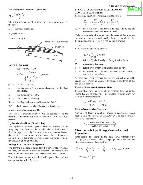
The aerodynamic moment is given by<br />
2<br />
Mρp C VAc<br />
M =<br />
2<br />
where the moment is taken about the front quarter point <strong>of</strong><br />
the airfoil.<br />
C M = moment coefficient<br />
A p = plan area<br />
c = chord length<br />
V<br />
α<br />
c<br />
4<br />
Reynolds Number<br />
Re = VD ρ µ = VD v<br />
( 2−n<br />
) n<br />
V D ρ<br />
Re′<br />
=<br />
, where<br />
n<br />
⎛ 3n<br />
+ 1⎞<br />
( n−1)<br />
K⎜<br />
⎟ 8<br />
⎝ 4n<br />
⎠<br />
ρ = the mass density,<br />
c<br />
AERODYNAMIC MOMENT CENTER<br />
CAMBER LINE<br />
CHORD<br />
D = the diameter <strong>of</strong> the pipe or dimension <strong>of</strong> the fluid<br />
streamline,<br />
µ = the dynamic viscosity,<br />
v = the kinematic viscosity,<br />
Re = the Reynolds number (Newtonian fluid),<br />
R e′<br />
= the Reynolds number (Power law fluid), and<br />
K and n are defined on page 44.<br />
The critical Reynolds number (Re)c is defined to be the<br />
minimum Reynolds number at which a flow will turn<br />
turbulent.<br />
Hydraulic Gradient (Grade Line)<br />
The hydraulic gradient (grade line) is defined as an<br />
imaginary line above a pipe so that the vertical distance<br />
from the pipe axis to the line represents the pressure head at<br />
that point. If a row <strong>of</strong> piezometers were placed at intervals<br />
along the pipe, the grade line would join the water levels in<br />
the piezometer water columns.<br />
Energy Line (Bernoulli Equation)<br />
The Bernoulli equation states that the sum <strong>of</strong> the pressure,<br />
velocity, and elevation heads is constant. The energy line is<br />
this sum or the "total head line" above a horizontal datum.<br />
The difference between the hydraulic grade line and the<br />
energy line is the V 2 / 2g term.<br />
47<br />
FLUID MECHANICS (continued)<br />
STEADY, INCOMPRESSIBLE FLOW IN<br />
CONDUITS AND PIPES<br />
The energy equation for incompressible flow is<br />
2<br />
p1<br />
V1<br />
p2<br />
V2<br />
+ z1<br />
+ = + z2<br />
+ +<br />
γ 2g<br />
γ 2g<br />
hf = the head loss, considered a friction effect, and all<br />
remaining terms are defined above.<br />
If the cross-sectional area and the elevation <strong>of</strong> the pipe are<br />
the same at both sections (1 and 2), then z1 = z2 and V1 = V2.<br />
The pressure drop p1 – p2 is given by the following:<br />
p1 – p2 = γ hf<br />
The Darcy-Weisbach equation is<br />
2<br />
f =<br />
L V<br />
h f = f , where<br />
D 2g<br />
f(Re, e/D), the Moody or Darcy friction factor,<br />
D = diameter <strong>of</strong> the pipe,<br />
L = length over which the pressure drop occurs,<br />
e = roughness factor for the pipe, and all other symbols<br />
are defined as before.<br />
A chart that gives f versus Re for various values <strong>of</strong> e/D,<br />
known as a Moody or Stanton diagram, is available at the<br />
end <strong>of</strong> this section.<br />
Friction Factor for Laminar Flow<br />
The equation for Q in terms <strong>of</strong> the pressure drop ∆pf is the<br />
Hagen-Poiseuille equation. This relation is valid only for<br />
flow in the laminar region.<br />
4<br />
πR<br />
∆p<br />
Q =<br />
8µ<br />
L<br />
f<br />
4<br />
πD<br />
∆p<br />
=<br />
128µ<br />
L<br />
Flow in Noncircular Conduits<br />
Analysis <strong>of</strong> flow in conduits having a noncircular cross<br />
section uses the hydraulic diameter DH, or the hydraulic<br />
radius RH, as follows<br />
cross - sectional area DH<br />
R H =<br />
=<br />
wetted perimeter 4<br />
Minor Losses in Pipe Fittings, Contractions, and<br />
Expansions<br />
Head losses also occur as the fluid flows through pipe<br />
fittings (i.e., elbows, valves, couplings, etc.) and sudden<br />
pipe contractions and expansions.<br />
2<br />
1<br />
2<br />
2<br />
p1<br />
V p2<br />
V<br />
+ z1<br />
+ = + z 2 + + h f + h<br />
γ 2g<br />
γ 2g<br />
h f , fitting =<br />
2<br />
V<br />
C<br />
2g<br />
f<br />
2<br />
h f<br />
f , fitting<br />
, where