fundamentals of engineering supplied-reference handbook - Ventech!
fundamentals of engineering supplied-reference handbook - Ventech!
fundamentals of engineering supplied-reference handbook - Ventech!

You also want an ePaper? Increase the reach of your titles
YUMPU automatically turns print PDFs into web optimized ePapers that Google loves.
MEASUREMENT<br />
Definitions:<br />
Transducer – a device used to convert a physical parameter<br />
such as temperature, pressure, flow, light intensity, etc. into<br />
an electrical signal (also called a sensor).<br />
Transducer sensitivity – the ratio <strong>of</strong> change in electrical<br />
signal magnitude to the change in magnitude <strong>of</strong> the physical<br />
parameter being measured.<br />
Resistance Temperature Detector (RTD) – a device used to<br />
relate change in resistance to change in temperature.<br />
Typically made from platinum, the controlling equation for<br />
an RTD is given by:<br />
( )<br />
RT= R0 ⎡<br />
⎣1+α T −T0<br />
⎤<br />
⎦ , where<br />
RT is the resistance <strong>of</strong> the RTD at temperature T (measured<br />
in °C)<br />
R0 is the resistance <strong>of</strong> the RTD at the <strong>reference</strong> temperature<br />
T0 (usually 0° C)<br />
α is the temperature coefficient <strong>of</strong> the RTD<br />
Strain Gauge – a device whose electrical resistance varies in<br />
proportion to the amount <strong>of</strong> strain in the device.<br />
Gauge factor (GF) – the ratio <strong>of</strong> fractional change in<br />
electrical resistance to the fractional change in length<br />
(strain):<br />
∆RR ∆RR<br />
GF = = , where<br />
∆L ε<br />
L<br />
R is the nominal resistance <strong>of</strong> the strain gauge at nominal<br />
length L<br />
∆R is the change in resistance due the change in length ∆L<br />
ε is the normal strain sensed by the gauge.<br />
The Gauge Factor for metallic strain gauges is typically<br />
around 2.<br />
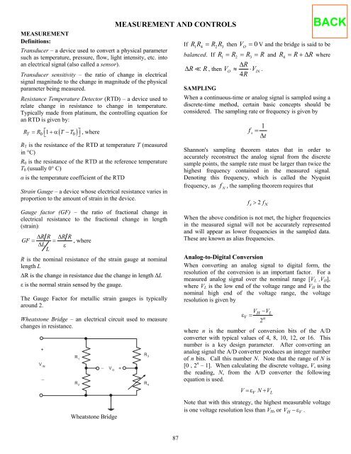
Wheatstone Bridge – an electrical circuit used to measure<br />
changes in resistance.<br />
+<br />
V IN<br />
−<br />
R 1<br />
R 2<br />
− V O<br />
Wheatstone Bridge<br />
MEASUREMENT AND CONTROLS<br />
+<br />
R 3<br />
R 4<br />
87<br />
If R1R4 = R2R3 then V O = 0 V and the bridge is said to be<br />
balanced. If R1 = R2 = R3 = R and R4 = R+∆ R where<br />
∆R � R , then<br />
∆R<br />
VO ≈ ⋅ VIN.<br />
4R<br />
SAMPLING<br />
When a continuous-time or analog signal is sampled using a<br />
discrete-time method, certain basic concepts should be<br />
considered. The sampling rate or frequency is given by<br />
f s =<br />
∆t<br />
1<br />
Shannon's sampling theorem states that in order to<br />
accurately reconstruct the analog signal from the discrete<br />
sample points, the sample rate must be larger than twice the<br />
highest frequency contained in the measured signal.<br />
Denoting this frequency, which is called the Nyquist<br />
frequency, as f N , the sampling theorem requires that<br />
f > 2 f<br />
s N<br />
When the above condition is not met, the higher frequencies<br />
in the measured signal will not be accurately represented<br />
and will appear as lower frequencies in the sampled data.<br />
These are known as alias frequencies.<br />
Analog-to-Digital Conversion<br />
When converting an analog signal to digital form, the<br />
resolution <strong>of</strong> the conversion is an important factor. For a<br />
measured analog signal over the nominal range [VL ,VH],<br />
where VL is the low end <strong>of</strong> the voltage range and VH is the<br />
nominal high end <strong>of</strong> the voltage range, the voltage<br />
resolution is given by<br />
V −V<br />
ε V =<br />
n<br />
2<br />
H L<br />
where n is the number <strong>of</strong> conversion bits <strong>of</strong> the A/D<br />
converter with typical values <strong>of</strong> 4, 8, 10, 12, or 16. This<br />
number is a key design parameter. After converting an<br />
analog signal the A/D converter produces an integer number<br />
<strong>of</strong> n bits. Call this number N. Note that the range <strong>of</strong> N is<br />
[0 , 2 n – 1]. When calculating the discrete voltage, V, using<br />
the reading, N, from the A/D converter the following<br />
equation is used.<br />
V = ε V N+ VL<br />
Note that with this strategy, the highest measurable voltage<br />
is one voltage resolution less than VH, or VH − ε V .