- Page 1 and 2:
q 11 Atomic Energy of Canada Limite
- Page 3 and 4:
ATOMIC ENERGY OF CANADA LIMITED FIF
- Page 5 and 6:
CINQUIEME CONFERENCE CANADIENNE SUR
- Page 7 and 8:
iii ACKNOWLEDGEMENT A special note
- Page 9 and 10:
DAY 2 KEYNOTE ADDRESS: Advanced Rad
- Page 11 and 12:
DAY1 KEYNOTE ADDRESS: Five Years Ex
- Page 13 and 14:
MB Power has a total generating cap
- Page 15 and 16: The fourth lesson learned was that
- Page 17 and 18: STATION UNIT Coleson Cove Coleson C
- Page 19 and 20: 0*'? - 8 - Ä | '••• '~-!.if~
- Page 21 and 22: - 10 - 7/8 inch Titanium Tube 3D i
- Page 23 and 24: The facility at CFB Greenwood was c
- Page 25 and 26: CONDITION MONITORING - 14 - The Con
- Page 27 and 28: - 16 - REDUCING UNWANTED EFFECTS ~
- Page 29 and 30: - 18 - When this happens, the instr
- Page 31 and 32: - 20 - (CJUIMTTCJW ROTOR BLADE SHOW
- Page 33 and 34: - 22 - Un»hl«ld«d prob* - good b
- Page 35 and 36: STEEL FASTENERS EXAMINATION OF FAST
- Page 37 and 38: - 26 - SKIP FINNED TUHt •< IG 5 I
- Page 39 and 40: To gain primary statistical informa
- Page 41 and 42: - 30 - The next step in the develop
- Page 43 and 44: Each firing of the capacitor banks
- Page 45 and 46: - 34 - At the Bruce we have complet
- Page 47 and 48: 1 GARTER SPRING IN VERTICAL POSITIO
- Page 49 and 50: DIGITAL READ OUT 3.595 TOIL ELEMENT
- Page 51 and 52: - 40 - EVALUATION OF ULTRASONIC MET
- Page 53 and 54: III MEASUREMENTS AND RESULTS - 42 -
- Page 55 and 56: C Real defects - 44 - Here we repor
- Page 57 and 58: Flaw Figure 1: Schematic of experim
- Page 59 and 60: 0.5 E10 Q. 8 1.5 2.0 - 48 - Positio
- Page 61 and 62: - 50 - Figure 6: Optical micrograph
- Page 63 and 64: - 52 - specialized applications suc
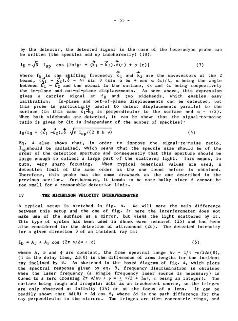
- Page 65: - 54 - As the probed surface is not
- Page 69 and 70: - 53 - bipolar pulse, as it is seen
- Page 71 and 72: - 60 - 18. J.-P. Monchalln and R. H
- Page 73 and 74: Sample Lens Ultrasound - 62 - Detec
- Page 75 and 76: CD CO c O Q. W 0 - 64 - Sin(7TfuT)
- Page 77 and 78: - 66 - AUTOMATED ULTRASONIC TESTING
- Page 79 and 80: - 68 - 2.1 Scanning Bridge and Imme
- Page 81 and 82: - 70 - each waveform digitization t
- Page 83 and 84: - 72 - Further development of the s
- Page 85 and 86: TRANSDUCER SELECT/ PULSE CONTROL -
- Page 87 and 88: SCAIIIIING BRIDGE COLOUR GRAPHICS D
- Page 89 and 90: Figure J — Beam profile of 3.5 MH
- Page 91 and 92: - 80 - an additional reverse magnet
- Page 93 and 94: - 82 - reinitialise the stress depe
- Page 95 and 96: BAR MAGNET IDEAL FIELDS MEASURED FI
- Page 97 and 98: - 86 - Figure 4: Hysteresis loops f
- Page 99 and 100: -150 H= 1.6 kA/m COMPRESSION -100 -
- Page 101 and 102: - 90 - MAGNETISATION ANHYSTERETÎC
- Page 103 and 104: (b) 19 mm diameter o Hard spot 19mm
- Page 105 and 106: Q. I CO zL 2 (Ky) TYPICAL UNCERTAIN
- Page 107 and 108: - 96 - Figure 14: Conceptual M-H be
- Page 109 and 110: - 98 - characterization program bas
- Page 111 and 112: - 100 - 1. Planar transducer: l.a.
- Page 113 and 114: Fig. 1 1/JS - 102 - Echos observed
- Page 115 and 116: - 104 - CAPABILITIES/LIMITATIONS OF
- Page 117 and 118:
- 106 - V = f* - 0.9 ak N [2] h. /^
- Page 119 and 120:
DISCUSSION - 108 - The results of t
- Page 121 and 122:
- 110 - FIGURE 1: Equipment Used fo
- Page 123 and 124:
FIGURE 4: - 112 - 5 10 IS 10 Depth
- Page 125 and 126:
FIGURE 6: Output of Computer Modell
- Page 127 and 128:
- 116 - "Events on earth consist in
- Page 129 and 130:
- 118 - now _n = Af (5) n where Af
- Page 131 and 132:
- 120 - REFERENCES 1. J.K. Feiblema
- Page 133 and 134:
PULSER IMMERSION TRANSDUCER WATER ^
- Page 135 and 136:
- 124 - 6. Ultrasonic frequency spe
- Page 137 and 138:
i I 1 i l - 126 - —j 10. Ultrason
- Page 139 and 140:
TIME RNFOSIS PLOT CRSF: - 128 - 1H.
- Page 141 and 142:
- 130 - THE INTRODUCTION OF REAL-TI
- Page 143 and 144:
5. QUALIFYING THE IMAGE - 132 - In
- Page 145 and 146:
- 134 - CONVENTIONAL FILM RADIOGRAP
- Page 147 and 148:
- 136 - 11.3 Computer Management of
- Page 149 and 150:
- 138 - Back end of system. The com
- Page 151 and 152:
- IAO - to be loaded properly into
- Page 153 and 154:
20. OPERATIONAL UTILIZATION - 142 -
- Page 155 and 156:
% -•'v/ FILM AND SCREENS ' \ INSI
- Page 157 and 158:
- 146 - By design, these A/E monito
- Page 159 and 160:
- 148 - a) enables an A/E monitor s
- Page 161 and 162:
- 150 - OTHER . CHANNELS CONVENTION
- Page 163 and 164:
DAY 2 KEYNOTE ADDRESS: Advanced Rad
- Page 165 and 166:
- 152 - ADVANCED RADIOGRAPHY FOR TR
- Page 167 and 168:
- 154 - for light weight and resist
- Page 169 and 170:
- 156 - available. Application exam
- Page 171 and 172:
- 158 - 28. V.J. Orphan, Science Ap
- Page 173 and 174:
CROSS SLIDE - 160 - AXIAL DRIVE : 3
- Page 175 and 176:
- 162 - Fig. 4. Two neutron radiogr
- Page 177 and 178:
INTRODUCTION (Continued) - 164 - Pr
- Page 179 and 180:
- 166 - SENSITOMETRIC QUALITY CONTR
- Page 181 and 182:
- 168 - MAKING THE TRANSITION TO AU
- Page 183 and 184:
(Continued) - 170 - The primary mec
- Page 185 and 186:
UJNXKAST o Indicated: o Calculated:
- Page 187 and 188:
- 174 - F»LM_i5=l£B_ DATE22=22=ß
- Page 189 and 190:
- 176 - RECENT MICROFUCUS X~RAY IMA
- Page 191 and 192:
ABSTRACT - 178 - WET CHANNEL INSPEC
- Page 193 and 194:
- 180 - 5) an eddy current probe to
- Page 195 and 196:
- 182 - tube, say 0.5-1.0 metre, so
- Page 197 and 198:
ACKNOWLEDGEMENTS - 184 - Many peopl
- Page 199 and 200:
- 186 - TABLE 3 Operational Objecti
- Page 201 and 202:
Pressure Tube Fuel -Carter Spring S
- Page 203 and 204:
«AC UUSU«O«HII INCUMKTM - 190 -
- Page 205 and 206:
Inlet or Outlet £nd Outlet 2m - 19
- Page 207 and 208:
- 194 - AN ADVANCED HEAT EXCHANGER
- Page 209 and 210:
- 196 - storage terminal. However,
- Page 211 and 212:
2.4 Data Processing Subsystem 2.4.1
- Page 213 and 214:
- 200 - display parameter set could
- Page 215 and 216:
5. PLAYBACK - 202 - A tape playback
- Page 217 and 218:
" * 0 0 MOkE* i SUN! SOW A 1 3* ~V
- Page 219 and 220:
SLHHT POU 422/14 - 206 - x •* F-R
- Page 221 and 222:
- 208 - The recent failure of a Zir
- Page 223 and 224:
- 210 - probe in its operating envi
- Page 225 and 226:
- 212 - The eddy current and wall t
- Page 227 and 228:
6. SUMMARY - 214 - The failure of a
- Page 229 and 230:
+2.5%p Lift Off •* - 216 - +5% Wa
- Page 231 and 232:
0 -0.2 -0.4 -0.6 -0.8 -1.0 c .1 2 o
- Page 233 and 234:
0 -0.25 -0.50 -0.75 -1.00 -1.25 i 1
- Page 235 and 236:
- 222 - CHECKING FOR CRACKS IN GAS
- Page 237 and 238:
- 224 - on the fringes. (The sensit
- Page 239 and 240:
Figure 1 18 MW gas turbine rotor, p
- Page 241 and 242:
- 228 - Figure 3 Weak penetrant ind
- Page 243 and 244:
- 230 - Figure 7 All signals superi
- Page 245 and 246:
- 232 - Figure 11 Frequency respons
- Page 247 and 248:
- 234 - row 3 sent to 0 4 n 1Vor?d.
- Page 249 and 250:
1. INTRODUCTION - 236 - In-service
- Page 251 and 252:
- 238 - treatment, and bending are
- Page 253 and 254:
- 240 - With an AC coil surrounding
- Page 255 and 256:
- 242 - against magnet position, tr
- Page 257 and 258:
6. SUMMARY - 244 - Conventional edd
- Page 259 and 260:
10 1 Centre Magnet 2 Keepers 3 End
- Page 261 and 262:
A - II' Concentric Groove 0.1 mm de
- Page 263 and 264:
- 250 ON THE RELATION BETWEEN ULTRA
- Page 265 and 266:
- 252 - Following a brief descripti
- Page 267 and 268:
CONCLUSION - 254 - In order to veri
- Page 269 and 270:
- 256 - 13. R.L. Smith, F.L. Rusbri
- Page 271 and 272:
Ultrasonic Instrumentation - 258 -
- Page 273 and 274:
100 a (m" 1 ) 10 f Slope = 4 10 - 2
- Page 275 and 276:
- 262 - ACOUSTIC EMISSION TESTING O
- Page 277 and 278:
- 264 - Metal components with class
- Page 279 and 280:
- 266 - Any recognizable fibre dama
- Page 281 and 282:
- 268 - FIGURE 1 EXPULSION OF FIBRE
- Page 283 and 284:
100 95 LU LU 5 S 90 ^"-85 K H H 80
- Page 285 and 286:
- 272 - FIGURE 6 SENSORS AND PREAMP
- Page 287 and 288:
900 800 700 i/> 600 H Z O 500 U 400
- Page 289 and 290:
- 276 - ACOUSTIC SORTING OF GRINDER
- Page 291 and 292:
- 278 - 6e P = Po c - St or p = p0
- Page 293 and 294:
- 280 - (9) for hardened steel. All
- Page 295 and 296:
- 282 - but not reseted, so the com
- Page 297 and 298:
- 284 - GOOD CRACKED 0 2 4 6 8 0 2
- Page 299 and 300:
0 - 286 - Figure 5: Resonance frequ
- Page 301 and 302:
- 288 - GOOD 0 .8 1.6 2.4 3.2 Level
- Page 303 and 304:
- 290 - THE BENEFITS OF NDT TRAININ
- Page 305 and 306:
- 292 - C.S.N.D.T. Chapters continu
- Page 307 and 308:
- 294 - The groundwork is in place.
- Page 309 and 310:
- 296 - The graduates of these prog
- Page 311 and 312:
- 298 - CERTIFICATION OF NONDESTRUC
- Page 313 and 314:
- 300 - (e) A differing but persist
- Page 315 and 316:
250 200 150 100 50 Magnetic Particl
- Page 317 and 318:
LOOKING INTO THE FUTURE R.S. Sh.an.
- Page 319 and 320:
- 305 - Another 'near future 1 need
- Page 321 and 322:
- 307 - NDE OF STRUCTURAL CERAMICS
- Page 323 and 324:
- 309 - The system described in thi
- Page 325 and 326:
and - 311 - S = a 2j for XR>a (2) S
- Page 327 and 328:
TRANSCEIVER digital signal display
- Page 329 and 330:
m "O -30 z o Ul -40 u. Ul ce o o Ü
- Page 331 and 332:
- 317 - deep penetration in same fo
- Page 333 and 334:
- 319 - the density by »w3 to 7%.
- Page 335 and 336:
density 10 3 kg/m 3 dissipation fac
- Page 337 and 338:
(0 60 g40 «MM "5. 3 O ü Cö §20
- Page 339 and 340:
60 PZT7 Vp " - 325 - o A —polariz
- Page 341 and 342:
- 327 -
- Page 343 and 344:
- 329 - Fig. 8: Typical Outputs of
- Page 345 and 346:
- 331 - ULTRASONIC ANALYSIS OF VOID
- Page 347 and 348:
- 333 - function is approximated by
- Page 349 and 350:
PULSER/RECEIVER OSCILLOSCOPE SPECTR
- Page 351 and 352:
to •a I a. a Ê £ < IS i-o 00 -
- Page 353 and 354:
Figure 5: Frequency spectra from: (
- Page 355 and 356:
- 341 - 100 150 Void Diameter (jjm)
- Page 357 and 358:
- 343 - TIME (ns) Figure 9: Peak ti
- Page 359 and 360:
- 345 - COMPUTER SIMULATION OF ULTR
- Page 361 and 362:
pu = T XX + T Xy tt x y pV = T Xy +
- Page 363 and 364:
- 349 - linear system of equations
- Page 365 and 366:
- 351 - These boundary conditions a
- Page 367 and 368:
10. EXAMPLE - 353 - The following e
- Page 369 and 370:
3 "/A ! - 355 - 1 I 2 I Figs. 1-4.
- Page 371 and 372:
INTRODUCTION - 357 - The inspection
- Page 373 and 374:
- 359 - A 3 by k array was construc
- Page 375 and 376:
INVERSION PROBLEM - 361 - The inver
- Page 377 and 378:
- 363 - the right of coils 1 to 6,
- Page 379 and 380:
—- ••;•••• 'IM i lüi
- Page 381 and 382:
- 3hl 2 3 4 OISTANCE (mm) Figure h.
- Page 383 and 384:
- 369 - a) 0.080 X 0.010 X 0.004" 5
- Page 385 and 386:
- 371 - DISTANCE ;,n(m) Figure 9b
- Page 387 and 388:
- 373 - INTRODUCTION X-ray diffract
- Page 389 and 390:
and - 375 - e a -^(a + a ) + —-
- Page 391 and 392:
- 377 - The commercial prototype is
- Page 393 and 394:
- 379 - REFERENCES 1) Klug, H.P. an
- Page 395 and 396:
- 381 - incident x-ray beam diffrac
- Page 397 and 398:
- 383 - Fig. 5(a). 200 W X-ray tube
- Page 399 and 400:
- 385 - Fig. 7. Head of the commerc
- Page 401 and 402:
- 387 - APPLICATIONS OF NEUTRON DIF
- Page 403 and 404:
peaks which are easily measurable.
- Page 405 and 406:
- 391 - directions around the circu
- Page 407 and 408:
I.-3 TRIPLE-AXIS NEUTRON SPECTROMET
- Page 409 and 410:
Ad hki£ d hkil xlO 3 - 395 - INTER
- Page 411 and 412:
- 397 - Fig. 5 Longitudinal, tangen
- Page 413 and 414:
I - INTRODUCTION - 399 - Polyethyle
- Page 415 and 416:
- 401 - This together with the expr
- Page 417 and 418:
- 403 - (5v/v)fit must be considere
- Page 419 and 420:
Transducer Signal - 405 - P.E.(p.v)
- Page 421 and 422:
ü .CO ü m O o CÖ g •4—> Q 2.
- Page 423 and 424:
- 409 - The present study was carri
- Page 425 and 426:
- 411 - Since tomographlc Images ar
- Page 427 and 428:
- 413 - bore axis, were scanned. Th
- Page 429 and 430:
- 415 - normally measured with a sh
- Page 431 and 432:
(a) L (b) ic) 1 - 417 - •HwK- |3A
- Page 433 and 434:
Figure A : Orientation of the casti
- Page 435 and 436:
- 421 - APPENDIX A Determination of
- Page 437 and 438:
ÜJ I/) 1 ce TO PE/ a. 100 90 - 80
- Page 439 and 440:
- 425 - This paper will concentrate
- Page 441 and 442:
- 427 - Ultrasonic and radiographie
- Page 443 and 444:
- 429 - A micrograph of the laminat
- Page 445 and 446:
- 431 - 2. Holography requires disp
- Page 447 and 448:
- 433 - 10. Green, D.R., Schneller,
- Page 449 and 450:
- 4 35 - Fig. 2 (a): cross-section
- Page 451 and 452:
10 _ 0.1 1_ 0.01 0.1 1 - 437 - TIME
- Page 453 and 454:
• •' '
- Page 455 and 456:
HEATING PULSES DETECTOR " -—FILTE
- Page 457 and 458:
- 443 - 5 10 POSITION (mm) Fig. 10
- Page 459 and 460:
- 445 - MATERIALS EFFECTS ON ACOUST
- Page 461 and 462:
- 447 - orientation of these specim
- Page 463 and 464:
- 449 - determined experimentally f
- Page 465 and 466:
STRUCTURE •^ TRANSDUCER (S) - 451
- Page 467 and 468:
- 453 - 500 PRESSURE (KPO) LEAK DIA
- Page 469 and 470:
Caron, V. Energy Mines & Resources
- Page 471 and 472:
Mclntyre, Dent Babcock & Wilcox Can
- Page 473:
ISSN 0067-0367 To identify individu