- Page 4:
CONTENTS PART I Chapter 1· Program
- Page 14:
viii
- Page 18:
Chapter 8 - COMMUNICATIONS OPTIONS
- Page 24:
6 5-4 3-1 o Interrupt Enable Memory
- Page 28:
PART I Chapter 2 Basic I/O Terminal
- Page 36:
2.2.3 Programming Examples Reading
- Page 40:
Model Type Power Descri ption L T33
- Page 50:
Punch Interrupt Service This interr
- Page 56:
LPII HIGH SPEED LINE PRINTER 19
- Page 68:
BIT 15 14 13 12 11 10 9 8 7 6 NAME
- Page 76:
LA30-DECwriter 29
- Page 82:
Ribbon: Code: Temperature: Humidity
- Page 88:
Figure 3"2 - DECtape Block Arrangem
- Page 98:
3-1 Function Bits o DO' Word Count
- Page 104:
Density: Data Capacity: Tape Motion
- Page 108:
TU 10 MAGTAPE UNIT 3.2.2 Operation
- Page 118:
10 End of Tape (EaT) 9 Record Lengt
- Page 122:
When the MTBRC is used in a space f
- Page 130:
4.2 STORAGE DISPLAY VTOIA The VT01A
- Page 134:
Brightness: Linearity: Deflection M
- Page 138:
Weight: Heat Dissipation: Operating
- Page 144:
PART I Chapter 5 Disk Storage Devic
- Page 156:
BIT 15 14 13 12 11 10 9 8 7 NAME Sp
- Page 166: RFll/RSll DECDISK 74
- Page 174: 7 Data Request Late (DRL) 6 Unused
- Page 178: (A stepdown autotransformer is prov
- Page 188: BIT 15 14 13 12 11 10 9 8 7 NAME Dr
- Page 196: 15-13 Drive Select (DR SEL) Contain
- Page 200: PART I Chapter 6 Clocks 6.1 PROGRAM
- Page 204: Count Set Buffer Register (Write On
- Page 208: ON: TST8 LKS 8PLON CLR8 LKS OFF: TS
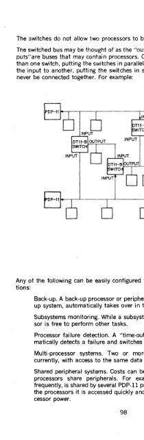
- Page 222: 7.2.3 Fail-Soft Operation The bus s
- Page 228: BIT *15 14 13 *12 *11 * 10 9 NAME T
- Page 234: 108
- Page 238: ety of asynchronous terminals or to
- Page 246: Receiver Buffer Register (RBUF) Tra
- Page 252: A Detect Answer option is used. The
- Page 258: tain an interrupt. It is cleared by
- Page 264:
2. Sync characters will be treated
- Page 270:
10-8 Bits Per Character 7 Receive D
- Page 278:
Modem Compatibility (Typical) Type
- Page 284:
only for use with the DC08CS distri
- Page 294:
memory used. For the MM'l1-F 950 na
- Page 304:
5-4 Memory Extension 3 Not Used 2 M
- Page 314:
Control Signals: Physical: Environm
- Page 318:
D. Telegraph Line Interfaces DEC NO
- Page 324:
PART I Chapter 9 Data Acquisition a
- Page 344:
9.3.3 Specifcations For D/ A Conver
- Page 356:
9.4.7 Specifications Modes of Opera
- Page 360:
2 UNIBUS AND INTERFACING 171
- Page 364:
PART II Introduction ..............
- Page 368:
PART II INTRODUCTION This section d
- Page 374:
Interrupt Requests Devices that gai
- Page 380:
Lines A specify a unique 16-bit wor
- Page 388:
a. Master sets C =00 for DATI or C=
- Page 398:
a. If immediate interrupt operation
- Page 402:
The bus master places address, cont
- Page 408:
TIME (ns) o 150 225 300 375 450 525
- Page 418:
200
- Page 428:
+5V TYPICAL UNIBUS DRIVER +5V TYPIC
- Page 432:
Figure 2-4 UNIBUS Jumper Module M92
- Page 448:
Table 2-3 Gating Control Signals Mo
- Page 460:
Figure 2-17 State Diagram of Master
- Page 466:
2.2.6 M795 Word Count and Bus· Add
- Page 470:
Table 2·6 M795 Output Signals Asse
- Page 482:
Signal Name BUS C ADRS TO BUS ADRS
- Page 494:
2.4 PDP·ll INTERFACE HARDWARE The
- Page 504:
2.4.2.5 External Device Cables-An e
- Page 518:
Signal levels used in the interface
- Page 524:
3.3.2 DRll-A Implementation A conve
- Page 538:
I\) O'l o READY (1) H START CONVERS
- Page 550:
nel and low COY) for a transfer fro
- Page 556:
5 through 1 of the UNIBUS-to-UNIBUS
- Page 566:
ation and each successive cycle of
- Page 578:
Second, the DRDB functions as a 16
- Page 582:
260 264 270 USER RESERVED 274 USER
- Page 586:
777410 RKBA 777406 RKWC 777404 RKCS
- Page 590:
772546 772544 772542 772540 772536
- Page 594:
770070 LATENCY TESTER 770056 TO 770
- Page 598:
TABLE B-2 UNIBUS PIN ASSIGNMENTS (B
- Page 602:
292
- Page 606:
RS64 Disk .........................