

PDP11 PeripheralsHbk 1972 - Trailing-Edge
PDP11 PeripheralsHbk 1972 - Trailing-Edge
PDP11 PeripheralsHbk 1972 - Trailing-Edge

Create successful ePaper yourself
Turn your PDF publications into a flip-book with our unique Google optimized e-Paper software.
a. If immediate interrupt operation is to be initiated, a device which has been se·<br />
lected as bus master asserts INTR and a vector address on the D lines, at the<br />
same time that it clears SACK and asserts BBSY. If data transfers occur prior<br />
to interrupt then SACK must remain asserted until INTR is asserted. If the de·<br />
vice has been making data transfers prior to the interrupt, it should assert<br />
SACK through the last cycle.<br />
b. The processor receives the INTR signal, waits 75 ns for deskew to ensure that<br />
a/l bits of the interrupt vector address are available, and asserts SSYN when<br />
the data is read in. :<br />
c. The bus master (interrupting device) receives SSYN and clears INTR, the D<br />
lines, and BBSY. This constitutes active release of the bus to the processor.<br />
d. The processor clears SSYN when INTR is cleared, and enters the interrupt se·<br />
quence to store the contents of the current PC and PS registers and replace<br />
them with the contents of the location specified by the vector address.<br />
1.3.3 Priority Chaining<br />
The PDp-ll uses electrical chaining of devices to assign minor priority levels.<br />
These levels separate devices of the same major priority level to provide a full ar·<br />
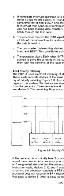
ray of priority servicing. Figure 1-8 illustrates the mode of operation and advan·<br />
tages of this system. Six devices are shown in order of their electrical distance<br />
from the processor. Three devices are at major priority level 4: device A, device C,<br />
and device D. The remaining three are at major priority level 5.<br />
f-BR5<br />
f-BR4<br />
r-BG5<br />
PROCESSOR -BG4 -<br />
DEVICE<br />
A<br />
LEVEL 4<br />
-<br />
DEVICE DEVICE DEVICE DEVICE<br />
B C D E<br />
LEVEL 5 LEVEL 4 LEVEL4 LEVEL 5<br />
Figure 1-8 Priority Chaining Example<br />
-<br />
DEVICE<br />
F<br />
LEVEL 5<br />
-<br />
TO NEXT<br />
DEVICE<br />
If the processor is at priority level 5 or above, no bus requests are granted from<br />
any of these devices. At a processor priority of 4, only requests from devices B, E,<br />
or F are granted. Assume that the processor priority is 2 and also that during one<br />
instruction cycle, devices C, E, and F assert bus requests. At the end of the in·<br />
struction, the processor conducts a PTR operation. Since BR 5 is asserted, the<br />
processor does not respond to BR 4 (device C). When BG 5 is asserted, the signal<br />
first goes to device B. After a delay to clock the interrupt control shift register<br />
190


