- Page 3: This page intentionally left blank
- Page 6 and 7: To My Wife Shanta Son Debojyoti and
- Page 8 and 9: Preface During the last fifty years
- Page 10 and 11: Contents Preface vii 1. Structure o
- Page 12 and 13: Contents xi 9. Symmetrical Componen
- Page 14 and 15: Structure of Power Systems and ew O
- Page 16 and 17: 1.2 REASONS OR INTERCONNECTION Stru
- Page 18 and 19: Structure of Power Systems and ew O
- Page 20 and 21: Case-1: If P 1 = P 2 = P 3 = ... =
- Page 22 and 23: Load factor, L = Maximum load = 3 M
- Page 24 and 25: \ LD = 1 MW (c) rom eqn.(1.13), coi
- Page 26 and 27: Case-2: Very short lasting peak. He
- Page 28 and 29: 1.9 DISADVANTAGES O LOW POWER ACTOR
- Page 30 and 31: Structure of Power Systems and ew O
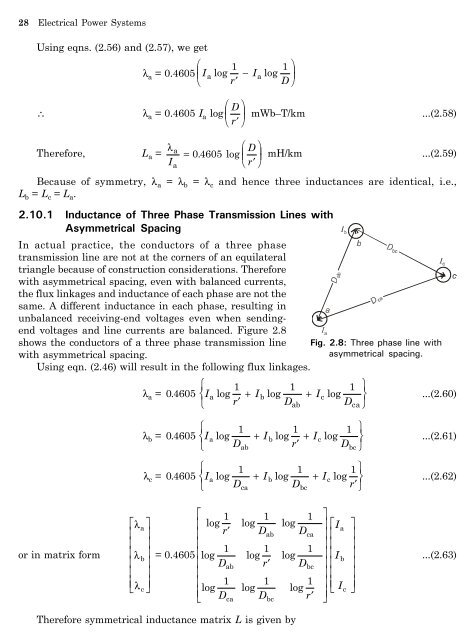
- Page 32 and 33: Resistance and Inductance of Transm
- Page 34 and 35: 2.4.1 Internal Inductance igure 2.1
- Page 36 and 37: Resistance and Inductance of Transm
- Page 38 and 39: Therefore, we can write L 1 = L 11
- Page 42 and 43: L = 0.4605 L Resistance and Inducta
- Page 44 and 45: =(2Dd 1 · 2Dd 1) 1/4 = (2 Dd 1) 1/
- Page 46 and 47: Solution. The distances from strand
- Page 48 and 49: Resistance and Inductance of Transm
- Page 50 and 51: Solution: Using eqn. (2.14), Hx = I
- Page 52 and 53: = 0.4605 log 6611 . 04 . Resistance
- Page 54 and 55: Resistance and Inductance of Transm
- Page 56 and 57: Resistance and Inductance of Transm
- Page 58 and 59: Since from symmetry D b1= D b2, l 1
- Page 60 and 61: \ D m = D D D D Resistance and Indu
- Page 62 and 63: dg 1 2 \ Dsa = 0. 7788 ´ 0. 015 ´
- Page 64 and 65: Resistance and Inductance of Transm
- Page 66 and 67: Capacitance of Transmission Lines 5
- Page 68 and 69: V Ki = 1 pÎ N å q m 2 o m = 1 3.3
- Page 70 and 71: Similarly for the 2nd transposition
- Page 72 and 73: Capacitance of Transmission Lines 5
- Page 74 and 75: C an = log R S| T| 00242 . 1 1 1 1
- Page 76 and 77: \ V12 = q ln pÎo \ C 12 = q \ C 12
- Page 78 and 79: I chg = jw C anV LN \ |I chg| = w C
- Page 80 and 81: Line length is 200 km. \ Can (total
- Page 82 and 83: Now applying eqn. (3.7), we have C
- Page 84 and 85: Capacitance of Transmission Lines 7
- Page 86 and 87: = 0.008993 m/km. Capacitance of Tra
- Page 88 and 89: Capacitance of Transmission Lines 7
- Page 90 and 91:
Capacitance of Transmission Lines 7
- Page 92 and 93:
Synchronous Machine: Steady State a
- Page 94 and 95:
Synchronous Machine: Steady State a
- Page 96 and 97:
Synchronous Machine: Steady State a
- Page 98 and 99:
\ V = 138 Using eqn. (4.18), . 3 =
- Page 100 and 101:
om ig. 4.6, Synchronous Machine: St
- Page 102 and 103:
Synchronous Machine: Steady State a
- Page 104 and 105:
Synchronous Machine: Steady State a
- Page 106 and 107:
\ i asy max = from which Synchronou
- Page 108 and 109:
Postfault voltage Synchronous Machi
- Page 110 and 111:
or the reference phase a, E a = (Z
- Page 112 and 113:
5.3 THE PER-UNIT (pu) SYSTEM Power
- Page 114 and 115:
Power System Components and Per Uni
- Page 116 and 117:
Power System Components and Per Uni
- Page 118 and 119:
Z L (pu) = Z L (ohm) (. 08+ j 03 .)
- Page 120 and 121:
Power System Components and Per Uni
- Page 122 and 123:
Power System Components and Per Uni
- Page 124 and 125:
Power System Components and Per Uni
- Page 126 and 127:
\ VL (pu) = 0. 2033 - 76. 68° pu P
- Page 128 and 129:
Base impedance for the load is ( )
- Page 130 and 131:
Now we can write, \ |I| cos f = P |
- Page 132 and 133:
Power System Components and Per Uni
- Page 134 and 135:
Power System Components and Per Uni
- Page 136 and 137:
Power System Components and Per Uni
- Page 138 and 139:
This is a simple series circuit. Th
- Page 140 and 141:
Eqns (6.15) and (6.17) can be writt
- Page 142 and 143:
Characteristics and Performance of
- Page 144 and 145:
om eqn. (6.6), Characteristics and
- Page 146 and 147:
as: \ |V S| = 145.13 kV. \ Sending
- Page 148 and 149:
Characteristics and Performance of
- Page 150 and 151:
Sending end power factor angle = 8.
- Page 152 and 153:
\ I R = V R = 208 Characteristics a
- Page 154 and 155:
6.6 VOLTAGE WAVES Characteristics a
- Page 156 and 157:
Characteristics and Performance of
- Page 158 and 159:
6.9 ERRANTI EECT Characteristics an
- Page 160 and 161:
Load low Analysis 7.1 INTRODUCTION
- Page 162 and 163:
Applying KCL to the independent nod
- Page 164 and 165:
y 10 = y 20 = y 30 = y13 ¢ y12 ¢
- Page 166 and 167:
\ V i = 1 Y ii L NM P - jQ i i * Vi
- Page 168 and 169:
n 2 i ii ii ik i k ik k i \ Pi - jQ
- Page 170 and 171:
Load low Analysis 157 ig. 7.6: P-re
- Page 172 and 173:
Load low Analysis 159 are permitted
- Page 174 and 175:
1 1 y13 = y31 = = = ( 10 - j30) Z (
- Page 176 and 177:
(1) \ V3 = 10011 . - 2. 06° After
- Page 178 and 179:
Load low Analysis 165 Using eqn. (7
- Page 180 and 181:
Load low Analysis 167 \ Q 2 = -|V 2
- Page 182 and 183:
|V 1| = 1.05,|V 2| = 1.0,|V 3| (1)
- Page 184 and 185:
\ L NM e j ( 0) ( 0) ( 0) 1 1 1 2 n
- Page 186 and 187:
( p) p The terms DPi and DQi Load l
- Page 188 and 189:
Load low Analysis 175 P2 = -35.77
- Page 190 and 191:
(1) P2( cal ) = -2.62 (1) P3( cal )
- Page 192 and 193:
Load low Analysis 179 Use deoupled
- Page 194 and 195:
0 Dd2 \ Dd3 0 ( ) ( ) NM \ 0 Dd2 L
- Page 196 and 197:
Assuming q ik - d i + d k » d ik,
- Page 198 and 199:
Table 7.4: Line impedances BUS code
- Page 200 and 201:
Symmetrical ault 187 is drawing 10
- Page 202 and 203:
\ X TH = ig. 8.4: Thevenin equivale
- Page 204 and 205:
ig. 8.5: Circuit diagram of Example
- Page 206 and 207:
= | Vo| | Vo| | Z| ´ × (MVA) Base
- Page 208 and 209:
\ 1 - V 1f = j0.14 × (-j4.165) \ V
- Page 210 and 211:
Base current I B = Per unit reactan
- Page 212 and 213:
Symmetrical ault 199 Example 8.9: T
- Page 214 and 215:
Solution: Let Base MVA = 12 Base Vo
- Page 216 and 217:
Solution: Let Base MVA = 100 Base V
- Page 218 and 219:
Therefore, current to be interrupte
- Page 220 and 221:
Circuit model under fault condition
- Page 222 and 223:
Symmetrical ault 209 Example 8.16:
- Page 224 and 225:
8.4 SHORT CIRCUIT ANALYSIS OR LARGE
- Page 226 and 227:
om equations. (8.9) and (8.10), we
- Page 228 and 229:
Using equation (8.14), Z BUS = L NM
- Page 230 and 231:
Symmetrical ault 217 Solution: Inje
- Page 232 and 233:
Hence, new Z = BUS 8.6.3 Type-3 Mod
- Page 234 and 235:
or L V 1 V M NM 2 V 0 n O QP = L ol
- Page 236 and 237:
Solution: (a) Using equation (8.11)
- Page 238 and 239:
Symmetrical ault 225 8.7 ig. 8.31 s
- Page 240 and 241:
has the following properties R S| T
- Page 242 and 243:
T stands for transpose. Using eqn.
- Page 244 and 245:
Using eqn.( 2.46) as given in Chapt
- Page 246 and 247:
Also I n = I a + I b + I c Using eq
- Page 248 and 249:
Symmetrical Components 235 ig. 9.4:
- Page 250 and 251:
Symmetrical Components 237 (b) - co
- Page 252 and 253:
Solution: I a + I b + I c = 0, I a
- Page 254 and 255:
Also note that I ab1 = I a1 3 30°
- Page 256 and 257:
Base voltage of transmission line 1
- Page 258 and 259:
Symmetrical Components 245 Example
- Page 260 and 261:
Symmetrical Components 247 Example
- Page 262 and 263:
9.5 Draw the zero-sequence network
- Page 264 and 265:
Unbalanced ault Analysis 251 Assumi
- Page 266 and 267:
The symmetrical components of the f
- Page 268 and 269:
Unbalanced ault Analysis 255 The bo
- Page 270 and 271:
ig. 10.9: Two conductors open. Unba
- Page 272 and 273:
Z 1 = j0.691 0.23 ´ 0. 691+ 0. 23
- Page 274 and 275:
Unbalanced ault Analysis 261 Exampl
- Page 276 and 277:
\ 3 ´ 1.0 ´ j0.4 j0.3 ´ j0.4 + j
- Page 278 and 279:
Denominator of eqns. (i) and (ii) Z
- Page 280 and 281:
Hence, rom eqn. (i), V b = V c Unba
- Page 282 and 283:
ig. 10.18 shows the sequence networ
- Page 284 and 285:
\ V b = E a = 3752.8 0° 1763 . - 3
- Page 286 and 287:
Unbalanced ault Analysis 273 ig. 10
- Page 288 and 289:
Unbalanced ault Analysis 275 10.4 A
- Page 290 and 291:
where J = moment of inertia of roto
- Page 292 and 293:
Power System Stability 279 Pi - Pe
- Page 294 and 295:
Power System Stability 281 (a) ind
- Page 296 and 297:
On a per-phase basis, power at the
- Page 298 and 299:
x eq = 0.25 + 0.15 + 02 . ´ 02 . 0
- Page 300 and 301:
Power System Stability 287 system.
- Page 302 and 303:
Power System Stability 289 or P i (
- Page 304 and 305:
\ d1 Pi (dc - d0 ) = z Pmax dc sin
- Page 306 and 307:
dcr z 1 d0 cr zbPi-Bgdd d dm = C -
- Page 308 and 309:
We know, K1 = Pmax In ig. 11.14, P
- Page 310 and 311:
Solution: Prefault operation x A =
- Page 312 and 313:
\ cosd cr = 0.654 Power System Stab
- Page 314 and 315:
Similarly, the change in the power
- Page 316 and 317:
d (2) = d (1) + Dd (2) = 17.855 + 1
- Page 318 and 319:
ig. 11.19: Sample network of 11.4.
- Page 320 and 321:
Automatic Generation Control: Conve
- Page 322 and 323:
12.4 ISOCHRONOUS GOVERNOR Automatic
- Page 324 and 325:
Automatic Generation Control: Conve
- Page 326 and 327:
Automatic Generation Control: Conve
- Page 328 and 329:
Where D = PL = constant. f Theref
- Page 330 and 331:
Automatic Generation Control: Conve
- Page 332 and 333:
\ T p = 32 3 sec. Automatic Generat
- Page 334 and 335:
Automatic Generation Control: Conve
- Page 336 and 337:
Automatic Generation Control: Conve
- Page 338 and 339:
Automatic Generation Control: Conve
- Page 340 and 341:
om ig. 12.20, state-variable equati
- Page 342 and 343:
The area control error for area-1 a
- Page 344 and 345:
Automatic Generation Control: Conve
- Page 346 and 347:
Automatic Generation Control: Conve
- Page 348 and 349:
Automatic Generation Control: Conve
- Page 350 and 351:
Automatic Generation Control: Conve
- Page 352 and 353:
Automatic Generation Control in a R
- Page 354 and 355:
Automatic Generation Control in a R
- Page 356 and 357:
Automatic Generation Control in a R
- Page 358 and 359:
Automatic Generation Control in a R
- Page 360 and 361:
Automatic Generation Control in a R
- Page 362 and 363:
Automatic Generation Control in a R
- Page 364 and 365:
Automatic Generation Control in a R
- Page 366 and 367:
Automatic Generation Control in a R
- Page 368 and 369:
Automatic Generation Control in a R
- Page 370 and 371:
Corona 357 air around the conductor
- Page 372 and 373:
14.4 POTENTIAL GRADIENT OR THREE-PH
- Page 374 and 375:
Similarly, G b = G c = r r V bn ln
- Page 376 and 377:
Corona 363 In the above expressions
- Page 378 and 379:
P c = 2.1f HG log 10 Vn DI HG r K
- Page 380 and 381:
Solution: rom eqn. (14.38), air den
- Page 382 and 383:
\ V 0 = 110.15 KV(rms) V n = 220 3
- Page 384 and 385:
\ W = 55 ´ b69. 28 - 57g 2 635 . -
- Page 386 and 387:
Analysis of Sag and Tension 15.1 IN
- Page 388 and 389:
where Dl = l0. DT MA DT = T1 - T0 T
- Page 390 and 391:
when x = L l , s = 2 2 , \ l 2 = H
- Page 392 and 393:
or approximately, 2 d = wL 8H ig. 1
- Page 394 and 395:
Squaring eqn. (15.37), we get, s 2
- Page 396 and 397:
under the action of T, H and wx. or
- Page 398 and 399:
\ T max = 572.59 kg (d) rom eqn. (1
- Page 400 and 401:
ig. 15.6: Case of negative x 1. Ana
- Page 402 and 403:
where Analysis of Sag and Tension 3
- Page 404 and 405:
or 1-meter length of conductor, Ana
- Page 406 and 407:
(f ) Vertical sag = dcos q cos q =
- Page 408 and 409:
Analysis of Sag and Tension 395 = 0
- Page 410 and 411:
Analysis of Sag and Tension 397 Ass
- Page 412 and 413:
Analysis of Sag and Tension 399 Dis
- Page 414 and 415:
Total weight of the conductor = wl
- Page 416 and 417:
Analysis of Sag and Tension 403 Whe
- Page 418 and 419:
Optimal System Operation 16.1 INTRO
- Page 420 and 421:
Optimal System Operation 407 where
- Page 422 and 423:
Optimal System Operation 409 2. The
- Page 424 and 425:
Complete algorithm is given below:
- Page 426 and 427:
DP g1 = Î 2 DP g2 = Î 2 Using Tay
- Page 428 and 429:
Optimal System Operation 415 Equati
- Page 430 and 431:
\ 2 C2 = 0.18 Pg2 + 32 Pg2 + K2 Whe
- Page 432 and 433:
Optimal System Operation 419 Equati
- Page 434 and 435:
DP L = rom eqns (16.36) and (16.39)
- Page 436 and 437:
Optimal System Operation 423 Now we
- Page 438 and 439:
Optimal System Operation 425 The pr
- Page 440 and 441:
Example 16.6: Consider Ex-16.5, wit
- Page 442 and 443:
\ DP g (l) = 264.1657 MW rom eqn. (
- Page 444 and 445:
\ (4) 2 2 P = 0.00005 × (188.95) +
- Page 446 and 447:
Optimal System Operation 433 The te
- Page 448 and 449:
\ Also d P 3 d 2 P 3 3 =- G 32 si
- Page 450 and 451:
Let the current in line K be I K1.
- Page 452 and 453:
+ HG I K Optimal System Operation
- Page 454 and 455:
Now, \ V1 = 1.198 14. 5º, \d1 = 14
- Page 456 and 457:
Optimal System Operation 443 B 11 =
- Page 458 and 459:
Z 1 = (0.03 + j0.12)pu; I 1 = (1.3
- Page 460 and 461:
Objective Questions Objective Quest
- Page 462 and 463:
Objective Questions 449 26. or a de
- Page 464 and 465:
Objective Questions 451 56. Peak lo
- Page 466 and 467:
82. Inductance of a conductor due t
- Page 468 and 469:
Objective Questions 455 108. In ter
- Page 470 and 471:
Objective Questions 457 137. In a p
- Page 472 and 473:
Objective Questions 459 (c) are var
- Page 474 and 475:
203. A system is said to be effecti
- Page 476 and 477:
Answers of Objective Questions 1. (
- Page 478 and 479:
Bibliography Bibliography 465 1. O.
- Page 480 and 481:
Index accelerating (or decelerating
- Page 482 and 483:
methods for voltage control 115 mul