5. Commands and Functions - Sanyo Denki America, Inc.
5. Commands and Functions - Sanyo Denki America, Inc.
5. Commands and Functions - Sanyo Denki America, Inc.

You also want an ePaper? Increase the reach of your titles
YUMPU automatically turns print PDFs into web optimized ePapers that Google loves.
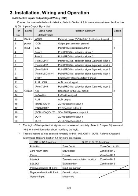
3. Installation, Wiring <strong>and</strong> Operation<br />
3.4.9 Control Input / Output Signal Wiring (CN1)<br />
Connect the user-selected control device. Refer to Section 4.1 for more information on this function.<br />
1) CN1 Input / Output Signal List<br />
Pin Signal Signal name<br />
Function summary<br />
Circuit<br />
No.<br />
(default value)<br />
1 Electric +COM External power (DC5V-24V) for the input signal -<br />
2 power -COM Output port common ground<br />
3 Input EXE Point/PRG execution number<br />
1<br />
4 Point1 Point/PRG No. selection signal 1<br />
5 Point2 Point/PRG No. selection signal 2<br />
6 (Point3)/IN1 Point/PRG No. selection signal 3/generic input 1<br />
7 (Point4)/IN2 Point/PRG No. selection signal 4/generic input 2<br />
8 (Point5)/IN3 Point/PRG No. selection signal 5/generic input 3<br />
9 (Point6)/SDN/IN4 Point/PRG No. selection signal 6/generic input 4<br />
10 STOP Emergency stop input (SOFF input)<br />
11 ALM CLR ALM cancel signal<br />
12<br />
(Point7)/IN5 Point/PRG No. selection signal 7/generic input 5<br />
13 Output Ack Response to the EXE signal<br />
2<br />
14 In-Position In-Position signal<br />
15 ALM ALM output<br />
16 (ZONE)/OUT1 ZONE/generic output 1<br />
17 (END)/OUT2 END/generic output 2<br />
18 (SON MON)/OUT3 SON MON/generic output 3<br />
19 OUT4 ZONE/generic output 4<br />
20<br />
OUT5 ZONE/generic output 5<br />
* The logic of the input/output signals can be selected remotely. Refer to Chapter 5 (comm<strong>and</strong><br />
16h) for more information about modifying the logic.<br />
* These functions can be selected remotely for IN1 - IN5, OUT1 - OUT<strong>5.</strong> Refer to Chapter 5<br />
(Comm<strong>and</strong> 16h) <strong>and</strong> Section 4.1 for more information.<br />
IN1 to IN5 functions<br />
OUT1 to OUT5 functions<br />
Point No. Zone Out 0 Zone Out 1 to 15<br />
Zero-return start END signal Zone No Bit 0<br />
Pause P.Busy Zone No Bit 1<br />
Interlock Zero-return completion monitor Zone No Bit 2<br />
SELECT SON monitor Zone No Bit 3<br />
Positive direction H. Limit Input pin monitor<br />
Negative direction H. Limit Generic output<br />
Generic input<br />
Motor stop<br />
3-9