- Page 1 and 2:
726+,%$ Telecommunication Systems D
- Page 3 and 4:
TOSHIBA AMERICA INFORMATION SYSTEMS
- Page 5 and 6:
Contents Introduction Organization.
- Page 7 and 8:
Contents Chapter 3 - Stratagy iES32
- Page 9 and 10:
Contents Chapter 6 - Voice Processi
- Page 11 and 12:
Contents Chapter 10 - Text-to-Speec
- Page 13 and 14:
Contents Chapter 14 - Token Program
- Page 15 and 16:
Contents Chapter 18 - Auxiliary Pro
- Page 17 and 18:
Introduction This Installation and
- Page 19 and 20:
Introduction Related Documents/Medi
- Page 21 and 22:
Overview 1 Overview This chapter co
- Page 23 and 24:
Overview Stratagy ES4, ES80, ES96,
- Page 25 and 26:
Overview Basic Features Basic Featu
- Page 27 and 28:
Overview Feature Groups This sectio
- Page 29 and 30:
Overview Feature Groups When a voic
- Page 31 and 32:
Overview Stratagy ES Hardware for S
- Page 33 and 34:
Overview Stratagy ES Hardware for S
- Page 35 and 36:
Overview Stratagy iES32 Hardware Vo
- Page 37 and 38:
Overview System Integration Configu
- Page 39 and 40:
Overview Exclusive Stratagy iES32 F
- Page 41 and 42:
Stratagy ES4, ES80, ES96, ES96R Ins
- Page 43 and 44:
Stratagy ES4, ES80, ES96, ES96R Ins
- Page 45 and 46:
Stratagy ES4, ES80, ES96, ES96R Ins
- Page 47 and 48:
10V Stratagy ES4, ES80, ES96, ES96R
- Page 49 and 50:
Stratagy ES4, ES80, ES96, ES96R Ins
- Page 51 and 52:
Stratagy ES4, ES80, ES96, ES96R Ins
- Page 53 and 54:
Stratagy ES4, ES80, ES96, ES96R Ins
- Page 55 and 56:
Stratagy ES4, ES80, ES96, ES96R Ins
- Page 57 and 58:
Stratagy ES4, ES80, ES96, ES96R Ins
- Page 59 and 60:
Stratagy ES4, ES80, ES96, ES96R Ins
- Page 61 and 62:
Stratagy iES32 Installation 3 WARNI
- Page 63 and 64:
Stratagy iES32 Installation Step 3:
- Page 65 and 66:
S_01 S_02 S_03 S_04 S_05 S_06 S_07
- Page 67 and 68:
Stratagy iES32 Installation Step 6:
- Page 69 and 70:
Stratagy iES32 Installation Step 11
- Page 71 and 72:
Stratagy iES32 Installation Step 12
- Page 73 and 74:
Stratagy iES32 Installation Step 13
- Page 75 and 76:
Using Stratagy ES Administration 4
- Page 77 and 78:
Using Stratagy ES Administration Ad
- Page 79 and 80:
Using Stratagy ES Administration Lo
- Page 81 and 82:
Using Stratagy ES Administration Co
- Page 83 and 84:
Using Stratagy ES Administration Cl
- Page 85 and 86:
Stratagy ES Configuration Menu 5 Th
- Page 87 and 88:
Configuration Wizard Stratagy ES Co
- Page 89 and 90:
Stratagy ES Configuration Menu Tele
- Page 91 and 92:
Stratagy ES Configuration Menu Tele
- Page 93 and 94:
Answer Methods Stratagy ES Configur
- Page 95 and 96:
Voice Ports Stratagy ES Configurati
- Page 97 and 98:
Serial Ports Stratagy ES Configurat
- Page 99 and 100:
Stratagy ES Configuration Menu Seri
- Page 101 and 102:
Stratagy ES Configuration Menu Noti
- Page 103 and 104:
Stratagy ES Configuration Menu Stat
- Page 105 and 106:
Stratagy ES Configuration Menu Holi
- Page 107 and 108:
Stratagy ES Configuration Menu Sche
- Page 109 and 110:
System Parameters Stratagy ES Confi
- Page 111 and 112:
Stratagy ES Configuration Menu Syst
- Page 113 and 114:
Stratagy ES Configuration Menu Syst
- Page 115 and 116:
Stratagy ES Configuration Menu Syst
- Page 117 and 118:
Stratagy ES Configuration Menu Syst
- Page 119 and 120:
Stratagy ES Configuration Menu Syst
- Page 121 and 122:
Stratagy ES Configuration Menu Syst
- Page 123 and 124:
Stratagy ES Configuration Menu Syst
- Page 125 and 126:
Voice Processing 6 This chapter giv
- Page 127 and 128:
Voice Processing Class of Service (
- Page 129 and 130:
Voice Processing Class of Service (
- Page 131 and 132:
Voice Processing User Mailbox Modif
- Page 133 and 134:
Voice Processing Mailbox Editor Men
- Page 135 and 136:
Voice Processing Mailbox Editor Scr
- Page 137 and 138:
Voice Processing Mailbox Editor Scr
- Page 139 and 140:
Voice Processing Mailbox Editor Scr
- Page 141 and 142:
Voice Processing Mailbox Editor Scr
- Page 143 and 144:
Voice Processing Mailbox Editor Scr
- Page 145 and 146:
Voice Processing Mailbox Editor Scr
- Page 147 and 148:
Voice Processing Mailbox Editor Scr
- Page 149 and 150:
Voice Processing Mailbox Editor Scr
- Page 151 and 152:
Voice Processing Mailbox Editor Scr
- Page 153 and 154:
Voice Processing Mailbox Editor Scr
- Page 155 and 156:
Voice Processing Mailbox Editor Scr
- Page 157 and 158:
Voice Processing Mailbox Editor Scr
- Page 159 and 160:
Voice Processing Mailbox Editor Scr
- Page 161 and 162:
Voice Processing Mailbox Editor Scr
- Page 163 and 164:
Voice Processing Mailbox Editor Scr
- Page 165 and 166:
Voice Processing Mailbox Editor Scr
- Page 167 and 168:
Voice Processing Mailbox Editor Scr
- Page 169 and 170:
Voice Processing Mailbox Editor Scr
- Page 171 and 172:
Voice Processing Distribution List
- Page 173 and 174:
Fax Server 7 Fax Server With the Fa
- Page 175 and 176:
Fax Server Fax Features AutoFax Pri
- Page 177 and 178:
Fax Server Step 4: Verify/Configure
- Page 179 and 180:
Fax Server Step 5: (Optional) Creat
- Page 181 and 182:
Fax Server Step 9: (Optional) Progr
- Page 183 and 184:
Automatic Speech Recognition (ASR)
- Page 185 and 186:
Automatic Speech Recognition (ASR)
- Page 187 and 188:
Automatic Speech Recognition (ASR)
- Page 189 and 190: Automatic Speech Recognition (ASR)
- Page 191 and 192: Unified Messaging (UM) 9 The Unifie
- Page 193 and 194: Unified Messaging (UM) Components M
- Page 195 and 196: Unified Messaging (UM) Installation
- Page 197 and 198: Unified Messaging (UM) Step 6: (Opt
- Page 199 and 200: Unified Messaging (UM) Step 7: Inst
- Page 201 and 202: Unified Messaging (UM) Step 9: Inst
- Page 203 and 204: Text-to-Speech (TTS) 10 Note The TT
- Page 205 and 206: Installation Important! TTS require
- Page 207 and 208: Text-to-Speech (TTS) Step 7: Verify
- Page 209 and 210: Interactive Voice Response (IVR) 11
- Page 211 and 212: IVR Hosts Interactive Voice Respons
- Page 213 and 214: Interactive Voice Response (IVR) An
- Page 215 and 216: Interactive Voice Response (IVR) IV
- Page 217 and 218: Advanced Integrations and Applicati
- Page 219 and 220: Advanced Integrations and Applicati
- Page 221 and 222: Advanced Integrations and Applicati
- Page 223 and 224: Advanced Integrations and Applicati
- Page 225 and 226: Advanced Integrations and Applicati
- Page 227 and 228: Advanced Integrations and Applicati
- Page 229 and 230: Advanced Integrations and Applicati
- Page 231 and 232: Voice and Resource Board Installati
- Page 233 and 234: Voice and Resource Board Installati
- Page 235 and 236: Voice and Resource Board Installati
- Page 237 and 238: Voice and Resource Board Installati
- Page 239: Voice and Resource Board Installati
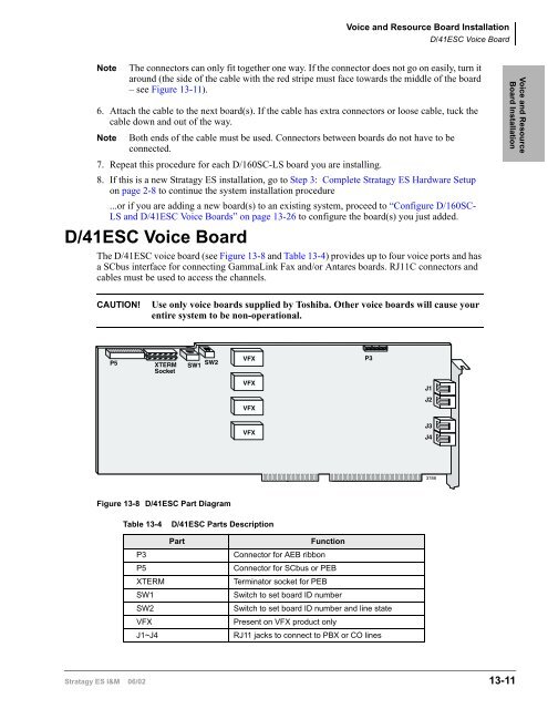
- Page 243 and 244: Voice and Resource Board Installati
- Page 245 and 246: Voice and Resource Board Installati
- Page 247 and 248: Voice and Resource Board Installati
- Page 249 and 250: Voice and Resource Board Installati
- Page 251 and 252: Voice and Resource Board Installati
- Page 253 and 254: Voice and Resource Board Installati
- Page 255 and 256: Voice and Resource Board Installati
- Page 257 and 258: Voice and Resource Board Installati
- Page 259 and 260: Voice and Resource Board Installati
- Page 261 and 262: Voice and Resource Board Installati
- Page 263 and 264: Token Programming 14 Stratagy ES’
- Page 265 and 266: Token Programming Singular Tokens T
- Page 267 and 268: Token Programming Replaced or Varia
- Page 269 and 270: Defined Tokens Token Programming De
- Page 271 and 272: Token Programming Defined Tokens Ta
- Page 273 and 274: Token Programming Defined Tokens Ta
- Page 275 and 276: Token Programming Defined Tokens Ta
- Page 277 and 278: Token Programming Defined Tokens Ta
- Page 279 and 280: Token Programming Defined Tokens Ta
- Page 281 and 282: Token Programming Defined Tokens Ta
- Page 283 and 284: Token Programming Defined Tokens Ta
- Page 285 and 286: Token Programming Defined Tokens Ta
- Page 287 and 288: System Reports 15 Stratagy ES syste
- Page 289 and 290: System Reports Report Option 1 Save
- Page 291 and 292:
System Reports Report Option 1 Port
- Page 293 and 294:
System Reports Report Option 1 Mail
- Page 295 and 296:
System Reports Report Option 1 Mail
- Page 297 and 298:
System Reports Report Option 1 Syst
- Page 299 and 300:
System Reports Report Option 2 Edit
- Page 301 and 302:
Maintenance and Upgrades 16 WARNING
- Page 303 and 304:
Maintenance and Upgrades Backup Ste
- Page 305 and 306:
Maintenance and Upgrades Stratagy E
- Page 307 and 308:
Maintenance and Upgrades Upgrade St
- Page 309 and 310:
Add Tape Drive Maintenance and Upgr
- Page 311 and 312:
Maintenance and Upgrades Add Tape D
- Page 313 and 314:
Maintenance and Upgrades Verify Mod
- Page 315 and 316:
Maintenance and Upgrades Stratagy E
- Page 317 and 318:
Maintenance and Upgrades Stratagy E
- Page 319 and 320:
Maintenance and Upgrades Stratagy E
- Page 321 and 322:
Replace Stratagy ES Hard Drive Main
- Page 323 and 324:
B101 B102 S101 S102 S103 S104 S105
- Page 325 and 326:
Troubleshooting 17 This chapter dis
- Page 327 and 328:
Troubleshooting Event Viewer Event
- Page 329 and 330:
Troubleshooting Performance Monitor
- Page 331 and 332:
Troubleshooting Verify Modem Data C
- Page 333 and 334:
Troubleshooting Stratagy Trace Date
- Page 335 and 336:
Troubleshooting Stratagy Trace View
- Page 337 and 338:
Troubleshooting TTS E-mail Feature
- Page 339 and 340:
Auxiliary Programs 18 This chapter
- Page 341 and 342:
Auxiliary Programs Stratagy ES Stan
- Page 343 and 344:
Auxiliary Programs Stratagy ES Stan
- Page 345 and 346:
Auxiliary Programs Stratagy ES Stan
- Page 347 and 348:
HyperTerminal Auxiliary Programs St
- Page 349 and 350:
Auxiliary Programs Stratagy iES32 S
- Page 351 and 352:
Appendix - Checklists/Forms Appendi
- Page 353 and 354:
Appendix - Checklists/Forms Pre-ins
- Page 355 and 356:
Index A accept_0_calling_id paramet
- Page 357 and 358:
Index E~G offset address, 13-7 part
- Page 359 and 360:
Index L~M IRQ settings, 2-12 ISA sl
- Page 361 and 362:
Index R~R sendfax_app_id, 7-6 sendf
- Page 363 and 364:
Index S~S speakname_dir parameter,
- Page 365 and 366:
Index U~U O( ) timed on-hook, 14-13


