

Telemecanique Altivar 56 manual - Northern Industrial
Telemecanique Altivar 56 manual - Northern Industrial
Telemecanique Altivar 56 manual - Northern Industrial

Create successful ePaper yourself
Turn your PDF publications into a flip-book with our unique Google optimized e-Paper software.
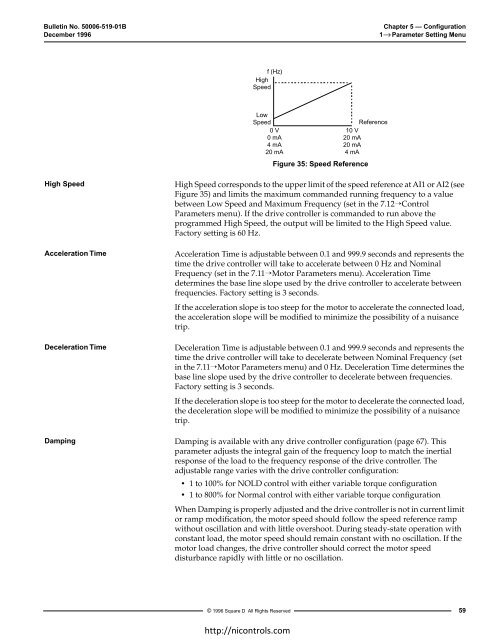
Bulletin No. 50006-519-01BChapter 5 — ConfigurationDecember 1996 1 → Parameter Setting Menuf (Hz)HighSpeedLowSpeed0 V0 mA4 mA20 mAReference10 V20 mA20 mA4 mAFigure 35: Speed ReferenceHigh SpeedAcceleration TimeDeceleration TimeDampingHigh Speed corresponds to the upper limit of the speed reference at AI1 or AI2 (seeFigure 35) and limits the maximum commanded running frequency to a valuebetween Low Speed and Maximum Frequency (set in the 7.12→ControlParameters menu). If the drive controller is commanded to run above theprogrammed High Speed, the output will be limited to the High Speed value.Factory setting is 60 Hz.Acceleration Time is adjustable between 0.1 and 999.9 seconds and represents thetime the drive controller will take to accelerate between 0 Hz and NominalFrequency (set in the 7.11→Motor Parameters menu). Acceleration Timedetermines the base line slope used by the drive controller to accelerate betweenfrequencies. Factory setting is 3 seconds.If the acceleration slope is too steep for the motor to accelerate the connected load,the acceleration slope will be modified to minimize the possibility of a nuisancetrip.Deceleration Time is adjustable between 0.1 and 999.9 seconds and represents thetime the drive controller will take to decelerate between Nominal Frequency (setin the 7.11→Motor Parameters menu) and 0 Hz. Deceleration Time determines thebase line slope used by the drive controller to decelerate between frequencies.Factory setting is 3 seconds.If the deceleration slope is too steep for the motor to decelerate the connected load,the deceleration slope will be modified to minimize the possibility of a nuisancetrip.Damping is available with any drive controller configuration (page 67). Thisparameter adjusts the integral gain of the frequency loop to match the inertialresponse of the load to the frequency response of the drive controller. Theadjustable range varies with the drive controller configuration:• 1 to 100% for NOLD control with either variable torque configuration• 1 to 800% for Normal control with either variable torque configurationWhen Damping is properly adjusted and the drive controller is not in current limitor ramp modification, the motor speed should follow the speed reference rampwithout oscillation and with little overshoot. During steady-state operation withconstant load, the motor speed should remain constant with no oscillation. If themotor load changes, the drive controller should correct the motor speeddisturbance rapidly with little or no oscillation.© 1996 Square D All Rights Reserved59ηττπ://νιχοντρολσ.χοm


