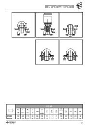
los tipos NB y SB, integrando enel circuito electrónico un interruptorestático que intervienedesactivando rápidamente elfreno en el caso de falta de tensión.Esta solución permite reducir eltiempo de desbloqueo del frenoevitando ulteriores cableados ycontactos externos.Para un mejor uso de los rectificadoresNBR y SBR es necesarioefectuar la alimentación delfreno independiente.Tensiones disponibles: 230V±10%, 400V ±10%, 50/60 Hz.tronic circuit incorporates astatic switch that de-energizesthe brake quickly in the eventvoltage is missing.This arrangement ensures shortbrake release response timewith no need for additional externalwiring and contacts.Optimum performance of rectifiersNBR and SBR is achievedwith separate brake power supply.Available voltages: 230V ± 10%,400V ± 10%, 50/60 Hz.Funktion der Typen NB und SB,indem in dem elektronischenSchaltkreis ein statischen Schalterintegriert ist, durch dessen Auslösendie Bremse im Fall einesSpannungsausfalls schnell abgeregtwird. Diese Lösung ermöglichteine Verringerung der Ansprechzeitender Bremse, wodurch weitereSchaltungen und externe Sensorenvermieden werden können.Im Hinblick auf einen besserenEinsatz der Gleichrichter NBR undSBR ist bei der Bremse eine separateVersorgung erforderlich.Verfügbare Spannungen: 230V ±10%, 400V ± 10%, 50/60 Hz.types NB et SB, en intégrantdans le circuit électronique uninterrupteur statique qui intervienten désexcitant rapidementle frein en cas de coupure detension.Cette solution permet de réduireles temps de déblocage du freinen évitant d’autres câblages etcontacts extérieurs.Pour une meilleure utilisationdes redresseurs NBR et SBRl’alimentation séparée du freinest nécessaire.Tensions disponibles : 230V ±10%, 400V ± 10%, 50/60 Hz.Datos técnicos del freno FDFD brake technical specificationsTechnische Daten -Bremstyp FDCaractéristiquesfreins FDtechniquesEn la tabla (A54) siguiente se indicanlas características técnicasde los frenos en c.c. tipo FD.(A54)FrenoBrakeBremseFreinPar de frenado M b [Nm]Brake torque M b [Nm]Bremsmoment M b [Nm]Couple de freinage M b [Nm]The table (A54) below reportsthe technical specifications ofDC brakes FD.DesbloqueoReleaseAnsprechzeitDéblocageIn der nachstehenden Tabelle(A54) werden die technischenDaten der Gleichstrombremsenvom Typ FD angegeben.FrenadaBrakingBremsungFreinageW máx por frenadaWmax per brake operationWmax pro BremsungWmax par freinageLe tableau (A54) suivant indiqueles caractéristiques techniquesdes freins en c.c. typeFD.muelles / springsfeder / ressortst 1 t 1s t 2 t 2c [J]6 4 2 [ms] [ms] [ms] [ms] 10 s/h 100 s/h 1000 s/h [MJ] [W]FD02 – 3.5 1.75 30 15 80 9 4500 1400 180 15 17FD03 5 3.5 1.75 50 20 100 12FD53 7.5 5 2.5 60 30 100 127000 1900 230 25 24FD04FD1415 10 5 80 35 140 15 10000 3100 350 30 33FD05 40 26 13 130 65 170 20FD15 40 26 13 130 65 170 20 18000 4500 500 50 45FD55 55 37 18 – 65 170 20FD06S 60 40 20 – 80 220 25 20000 4800 550 70 55FD5675 3790 150 20––FD06 100 50 100 150 2029000 7400 800 80 65FD07 150 100 50 – 120 200 25 40000 9300 1000 130 65FD08* 250 200 170 – 140 350 30 60000 14000 1500 230 100FD09** 400 300 200 – 200 450 40 70000 15000 1700 230 120WP* valores de par de frenado con 9, 7y 6 muelles respectivamente.** valores de par de frenado con 12, 9y 6 muelles respectivamente. brake torque values obtainedwith 9, 7 and 6 springs, respectively brake torque values obtainedwith 12, 9 and 6 springs, respectively Werte, der durch den Einsatz vonjeweils 9, 7, 6 Federn erreichtenBremsmomente Werte, der durch den Einsatz vonjeweils 12, 9, 6 Federn erreichtenBremsmomente valeurs de couple de freinage obtenuesrespectivement avec n° 9,7, 6 ressorts valeurs de couple de freinage obtenuesrespectivement avec n° 12,9, 6 ressortsLeyenda:t 1 = tiempos de desbloqueo del frenocon alimentador de semiondat 1s = tiempos de desbloqueo del frenocon dispositivo con alimentadorde la excitación a controlelectrónicot 2 = retardo de la frenada con interrupciónlado c.a. y alimentaciónindependientet 2c = retardo de la frenada con interrupciónlado c.a. y c.c. – Losvalores t 1,t 1s, t 2,t 2c indicadosen la tabla (A54) se refieren alfreno tarado al par máximo, entrehierromedio y tensión nominalW max = energía máxima por frenadaW = energía de frenada entre dosregulaciones sucesivas del entrehierroP b = potencia absorbida por el frenoa 20ºCM b = par de frenado estático (±15%)s/h = arranques horaKey: Zeichenerklärung: Légende:t 1 = brake release time withhalf-wave rectifiert 1s = brake release time withover-energizing rectifiert 2 = brake engagement time withAC line interruption and separatepower supplyt 2c = brake engagement time withAC and DC line interruption –Values for t 1,t 1s,t 2,t 2c indicatedin the tab. (A54) are referred tobrake set at maximum torque,medium air gap and rated voltageW max = max energy per brake operationW = braking energy between twosuccessive air gap adjustmentsP b = brake power absorption at 20 °CM b = static braking torque (±15%)s/h = starts per hourt 1= Ansprechzeit der Bremse mitHalbwellengleichrichtert 1s = Ansprechzeit der Bremse mitelektronisch gesteuerten Erregungsgleichrichtert 2 = Bremsverzögerung mit Unterbrechungauf Wechselstromseiteund Fremdversorgungt 2c = Bremsverzögerung mit Unterbrechungauf WechselstromundGleichstromseite – Die inder Tab. (A54) angegebenenWerte t 1,t 1s, t 2,t 2c beziehensich auf eine auf das max.Bremsmoment geeichte Bremse,mit mittlerem Luftspalt undNennspannungW max = max. Energie pro BremsungW = Bremsenergie zwischen zweiEinstellungen des LuftspaltsP b = bei 20° C von der Bremse aufgenommeneLeistung (50 Hz)M b = statisches Bremsmoment (±15%)s/h = Einschaltungen pro stundet 1= temps de déblocage du freinavec dispositif d’alimentation àdemi-ondet 1s = temps de déblocage du frein avecdispositif d’alimentation à contrôleélectronique de l’excitationt 2 = retard de freinage avec interruptioncôté c.a. et alimentationséparéet 2c = retard de freinage avec interruptioncôté c.a. et c.c. – Les valeursde t 1,t 1s, t 2,t 2c indiquées dans letab. (A54) se réfèrent au frein étalonnéau couple maximal, entrefermoyen et tension nominaleW max = énergie max. par freinageW = énergie de freinage entre deuxréglages successifs del’entreferP b = puissance absorbée par lefreinà20°CM b = couple de freinage statique(±15%)s/h = dèmarrages horaires86
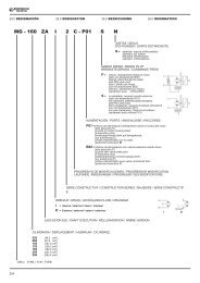
Conexiones del freno FDFD brake connectionsAnschlüsse - Bremstyp FDRaccordements frein FDLos motores estándar de una velocidad,se suministran con la conexióndel rectificador a la cajade bornes realizada en fábrica.Para los motores de 2 velocidades,y donde se requiera la alimentaciónindependiente del freno,prever la conexión al rectificadorde acuerdo con la tensióndel freno V B indicada en la placadel motor.Dada la naturaleza inductivade la carga, para el mando delfreno y para la interrupciónlado corriente continua, debenutilizarse contactos concategoría de uso AC-3 segúnIEC 60947-4-1.Tabla (A55) – Alimentación delfreno desde los bornes del motore interrupción lado c.aTiempo de parada t 2 retardadoen función de las constantes detiempo del motor. Debe preversecuando se requieran arranques/paradasprogresivos.Tabla (A 56) - Bobina del frenocon alimentación independientee interrupción del lado c.a.Tiempo de parada normal e independientedel motor.Los tiempos de paro t 2 están indicadosen la tabla (A54).Tabla (57) - Bobina freno con alimentaciónindependiente e interrupcióndel lado c.a. y c.c.Tiempo de parada reducido segúnlos valores t 2c indicados enla tabla (A54).Tabla (A58) – Bobina de frenocon alimentación separada e interrupciónlado c.a. y c.c.Tiempo de parada reducido segúnlos valores t 2c indicados en latabla (A54).On standard single-pole motors,the rectifier is connected to themotor terminal board at the factory.For switch-pole motors andwhere a separate brake powersupply is required, connection torectifier must comply with brakevoltage V B stated in motor nameplate.Because the load is of the inductivetype, brake controland DC line interruption mustuse contacts from the usageclass AC-3 to IEC 60947-4-1.Table (A55) – Brake power supplyfrom motor terminals and ACline interruptionDelayed stop time t 2 and functionof motor time constants.Mandatory when soft-start/stopsare required.Table (A56) – Brake coil withseparate power supply and ACline interruptionNormal stop time independent ofmotor.Achieved stop times t 2 are indicatedin the table (A54).Table (A57) – Brake coil powersupply from motor terminals andAC/DC line interruption.Quick stop with operation timest 2c as per table (A54).Table (A58) – Brake coil withseparate power supply andAC/DC line interruption.Stop time decreases by valuest 2c indicated in the table (A54).Die einpoligen Motoren werdenvom Werk ab mit an die MotorspannungangeschlossenemGleichrichters geliefert.Für die polumschaltbaren Motoren,und Bremse mit separaterVersorgung, wird in Übereinstimmungmit der auf dem Typenschilddes Motors angegebenen BremsspannungV B der Anschluss anden Gleichrichter vorgesehen.Da es sich bei der Bremsleistungumeine induktive Krafthandelt, müssen gemäß IEC60947-4-1 für die Steuerungder Bremse und die UnterbrechungderGleichstromseiteKontakte der Kategorie AC-3verwendet werden.Tabelle (A55) –Bremsversorgungüber die Motorspannung und Unterbrechungder Wechselstromseite.Verzögerter und von den Zeitkonstantendes Motors abhängigeHaltezeit t 2 .Vorzusehen, wenn progressiveStarts/Stopps erforderlich sind.Tabelle (A56) – Bremsspule mit separaterSpannungsversorgung undUnterbrechung der Wechselstromseite.Normale und vom Motor unabhängigeStoppzeiten. Es werdendie in der Tabelle (A54) angegebenenStoppzeiten t 2 realisiert.Tabelle (A57) – Bremsspule mitVersorgung über die Motorspannungund Unterbrechung derGleich- und der Wechselstromseite.Schneller Stopp mit den in der Tabelle(A54) angegebenen Ansprechzeitent 2c .Tabelle (A58) - Bremsspule mit separaterSpannungsvversorgungund Unterbrechung der Gleich- undder Wechselstromseite. ReduzierteStoppzeiten der in der Tabelle(A54) angegebenen Werte t 2c .(A55) (A56) (A57) (A58)Les moteurs standard à une vitessesont fournis avec le raccordementdu redresseur au borniermoteur déjà réalisé en usine.Pour les moteurs à 2 vitesses, etlorsqu’une alimentation séparéedu frein est requise, prévoir le raccordementau redresseur conformémentàlatensionfreinVB indiquéesur la plaque signalétiquedu moteur.Etant donné la nature inductivede la charge, pour la commandedu frein et l’interruptioncôté courant continu, il est nécessaired’utiliser des contactsavec catégorie d’utilisationAC-3 selon la norme IEC60947-4-1.Tableau (A55) - Alimentationfrein depuis bornes moteur et interruptioncôté c.a.Temps d’arrêt t 2 retardé et fonctiondes constantes de temps dumoteur.A prévoir lorsque des démarrages/arrêtsprogressifs sont requis.Tableau (A56) - Bobine de freinavec alimentation séparée et interrupteurcôté c.a.Temps d’arrêt normal et indépendantdu moteur.Les temps d’arrêts t 2 sont ceuxindiqués dans le tableau (A54).Tableau (A57) - Bobine de freinavec alimentation depuis lesbornes moteur et interruptioncôté c.a. et c.c.Arrêt rapide avec les temps d’interventiont 2c indiqués dans le tableau(A54).Tableau (A58) - Bobine de freinavec alimentation séparée et interruptioncôté c.a. et c.c.Temps d’arrêt réduit selon lesvaleurs t 2c indiquées dans le tableau(A54).bobinacoilSpulebobinebobinacoilSpulebobinebobinacoilSpulebobinebobinacoilSpulebobineEn las tablas de (A55) a (A58)están representados los esquemastípicos de conexión parauna alimentación de 400 V, motores230/400V conectados enestrella y freno a 230V.Tables (A55) through (A58)show the typical connection diagramsfor 400 V power supply,star-connected 230/400V motorsand 230 V brake.In den Tabellen (A55) bis (A58)werden die typischen Schaltungenfür Versorgung mit 400 V,Motoren 230/400V mit Sternschaltungund einer Bremsspannungvon 230 V wiedergegeben.Les tableaux de (A55) à (A58)indiquent les schémas typiquesde branchement pour une alimentationde 400 V, moteurs230/400V raccordés en étoile etfrein 230 V.87