Workshop proceeding - final.pdf - Faculty of Information and ...
Workshop proceeding - final.pdf - Faculty of Information and ...
Workshop proceeding - final.pdf - Faculty of Information and ...

You also want an ePaper? Increase the reach of your titles
YUMPU automatically turns print PDFs into web optimized ePapers that Google loves.
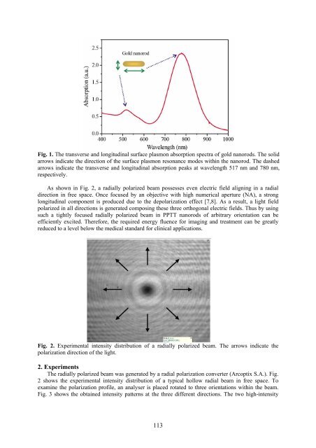
Fig. 1. The transverse <strong>and</strong> longitudinal surface plasmon absorption spectra <strong>of</strong> gold nanorods. The solid<br />
arrows indicate the direction <strong>of</strong> the surface plasmon resonance modes within the nanorod. The dashed<br />
arrows indicate the transverse <strong>and</strong> longitudinal absorption peaks at wavelength 517 nm <strong>and</strong> 780 nm,<br />
respectively.<br />
As shown in Fig. 2, a radially polarized beam possesses even electric field aligning in a radial<br />
direction in free space. Once focused by an objective with high numerical aperture (NA), a strong<br />
longitudinal component is produced due to the depolarization effect [7,8]. As a result, a light field<br />
polarized in all directions is generated composing these three orthogonal electric fields. Thus by using<br />
such a tightly focused radially polarized beam in PPTT nanorods <strong>of</strong> arbitrary orientation can be<br />
efficiently excited. Therefore, the required energy fluence for imaging <strong>and</strong> treatment can be greatly<br />
reduced to a level below the medical st<strong>and</strong>ard for clinical applications.<br />
Fig. 2. Experimental intensity distribution <strong>of</strong> a radially polarized beam. The arrows indicate the<br />
polarization direction <strong>of</strong> the light.<br />
2. Experiments<br />
The radially polarized beam was generated by a radial polarization converter (Arcoptix S.A.). Fig.<br />
2 shows the experimental intensity distribution <strong>of</strong> a typical hollow radial beam in free space. To<br />
examine the polarization pr<strong>of</strong>ile, an analyser is placed rotated to three orientations within the beam.<br />
Fig. 3 shows the obtained intensity patterns at the three different directions. The two high-intensity<br />
113