IGCAR : Annual Report - Indira Gandhi Centre for Atomic Research
IGCAR : Annual Report - Indira Gandhi Centre for Atomic Research
IGCAR : Annual Report - Indira Gandhi Centre for Atomic Research

You also want an ePaper? Increase the reach of your titles
YUMPU automatically turns print PDFs into web optimized ePapers that Google loves.
IGC<br />
<strong>Annual</strong> <strong>Report</strong> 2007<br />
characterization is not possible.<br />
This problem has been<br />
successfully overcome at the<br />
Quality Assurance Division<br />
using a novel combination of<br />
TOFD and immersion. The<br />
principle is illustrated as a<br />
schematic sketch in Fig.1.<br />
For initial studies, three<br />
stainless steel plates with<br />
artificial reference defects were<br />
chosen. Plate 1 was 10 mm<br />
thick and had five side drilled<br />
holes of 2 mm diameter at<br />
different locations. Plate 2 was<br />
5 mm thick with 5% and 10%<br />
notches and two side drilled<br />
holes (2 mm diameter) and<br />
Plate 3 was 3 mm thick with a<br />
5% and 10% notch. Since the<br />
plates were quite large and the<br />
region of interest was small, to<br />
maintain the required water<br />
path, a dam was constructed.<br />
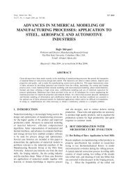
Fig. 2(a) shows the<br />
experimental setup.<br />
Fig.1 Beam path and angle of propagation through water and<br />
material in the immersion TOFD experiment<br />
The parameters to be<br />
considered were thickness of<br />
the water column over the<br />
material and probe tilt (Fig.1).<br />
Based on the time of flight<br />
equations, the time difference<br />
between lateral wave and back<br />
wall echo was computed as a<br />
function of probe tilt <strong>for</strong><br />
specimens of different<br />
thickness. It was observed that<br />
as the probe separation and the<br />
propagation angle inside the<br />
material decreases, this time<br />
difference increases which<br />
leads to better spatial<br />
resolution (Table1).<br />
Fig.2 (a) Experimental setup (b) 3.15 mm thick welded hexagonal sheath<br />
(c) TOFD image of a welded plate having no defect (slop is due to<br />
curvature of the plate) and (d) TOFD images indicating lack of<br />
penetration and porosity.<br />
The required lower probe<br />
separations were not possible<br />
in conventional TOFD because<br />
of the size of the probes. Based<br />
on the experiments on the<br />
reference specimens, further<br />
examinations were carried out<br />
on welded specimens of<br />
thickness 3.15mm. These<br />
specimens pertain to the<br />
hexagonal sheath of the dummy<br />
fuel sub-assembly. The weld<br />
specimens had defects such as<br />
lack of penetration and porosity<br />
ENABLING TECHNOLOGIES 117