IGCAR : Annual Report - Indira Gandhi Centre for Atomic Research
IGCAR : Annual Report - Indira Gandhi Centre for Atomic Research
IGCAR : Annual Report - Indira Gandhi Centre for Atomic Research

You also want an ePaper? Increase the reach of your titles
YUMPU automatically turns print PDFs into web optimized ePapers that Google loves.
IGC<br />
<strong>Annual</strong> <strong>Report</strong> 2007<br />
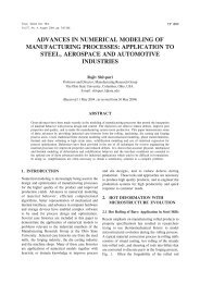
system are analyzed. Fault Tree<br />
Analysis, shown in Fig.2, is a<br />
Top down approach, where the<br />
failure of system in a particular<br />
mode is taken as top event and<br />
the causes of that failure along<br />
with the interrelation between<br />
the causes are analyzed until<br />
we reach the basic causes.<br />
Apart from these qualitative<br />
methods there are many<br />
quantitative reliability analysis<br />
methods used to compare<br />
different topologies, and<br />
evaluate the probability of<br />
failure on demand.<br />
Calculation of Failure rate<br />
<strong>for</strong>ms the basis <strong>for</strong> Quantitative<br />
reliability analysis. For<br />
electronic components, US MIL<br />
217-F Notice-2 standard<br />
provides empirical <strong>for</strong>mulae to<br />
find out the failure rate.<br />
Reliability prediction of<br />
electronic components is done<br />
by Parts Stress Method or Parts<br />
Count Method. In case, <strong>for</strong> any<br />
component, if the failure rate is<br />
not available, failure rate data<br />
given by the manufacturer is<br />
used in the calculations. While<br />
arriving at the failure rate, the<br />
derating of the component,<br />
quality level, temperature and<br />
intended environment are taken<br />
into consideration.<br />
IEC 61508 provides<br />
guidelines <strong>for</strong> the determination<br />
of probability of unsafe state of<br />
the system. Using these<br />
guidelines, the probability of<br />
unsafe state can be calculated<br />
at different conditions.<br />
Verification and Validation of<br />
the Software and Hardware<br />
should be done to verify<br />
Fig.1 Example Fault Tree model<br />
whether the system is matching<br />
the requirements or not.<br />
The reliability analysis of<br />
Safety Logic Systems and Core<br />
Temperature Monitoring system<br />
proved the safety of the system<br />
theoretically. The results are<br />
used as inputs in the Level 1<br />
Probabilistic Safety Assessment<br />
of PFBR.<br />
V.C.4. Safety Logic with Fine Impulse Test<br />
System <strong>for</strong> PFBR<br />
PFBR is provided with two<br />
independent, fast acting and<br />
diverse shutdown systems<br />
namely SDS-1 & SDS-2 to<br />
detect any abnormalities in<br />
reactor core and to initiate<br />
safety action. Each system<br />
consists of sensors, signalprocessing<br />
systems, logic<br />
systems, drive mechanisms and<br />
absorber rods. The absorber<br />
rods of the first system are<br />
Control and Safety Rods (CSR)<br />
and that of the second are<br />
called as Diverse Safety Rods<br />
(DSR). There are nine CSR and<br />
three DSR. While CSR are used<br />
<strong>for</strong> startup, control of reactor<br />
power, controlled shutdown<br />
and SCRAM, the DSR are used<br />
only <strong>for</strong> SCRAM. The<br />
respective drive mechanisms<br />
are called as CSRDM &<br />
DSRDM. For SDS-1, Safety<br />
Logic with Fine Impulse Test<br />
(SLFIT) System is provided<br />
whereas <strong>for</strong> SDS-2, Pulse<br />
Coded Safety Logic (PCSL)<br />
System is provided.<br />
SLFIT system receives trip<br />
parameters from neutron flux<br />
monitoring, failed fuel<br />
detection, sodium flow<br />
monitoring, reactor inlet<br />
temperature monitoring systems<br />
130 ENABLING TECHNOLOGIES