IGCAR : Annual Report - Indira Gandhi Centre for Atomic Research
IGCAR : Annual Report - Indira Gandhi Centre for Atomic Research
IGCAR : Annual Report - Indira Gandhi Centre for Atomic Research

You also want an ePaper? Increase the reach of your titles
YUMPU automatically turns print PDFs into web optimized ePapers that Google loves.
IGC<br />
<strong>Annual</strong> <strong>Report</strong> 2007<br />
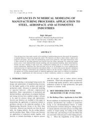
Fig.1 Schematic of the RV cooling system<br />
emerges out of the insulation.<br />
To mitigate this hot spot, it was<br />
essential to increase the<br />
circumferential conductance in<br />
the RV liner. This is achieved by<br />
interconnecting the cooling<br />
pipes by 10 mm thick carbon<br />
steel plates <strong>for</strong> a height of 1.2<br />
m, as shown in Fig. 1. Also, the<br />
water flow rate has to be<br />
doubled <strong>for</strong> the lower lateral<br />
shield region of RV. The number<br />
of cooling tubes and the water<br />
flow rate in the additional<br />
cooling loop of SVSE have been<br />
determined to be 288 and 60<br />
m 3 /h respectively. The<br />
temperature distribution in RV<br />
with these modifications is<br />
depicted in Fig. 2.<br />
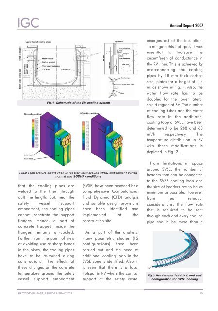
Fig.2 Temperature distribution in reactor vault around SVSE embedment during<br />
normal and SGDHR conditions<br />
that the cooling pipes are<br />
welded to the liner (through<br />
out) the length. But, near the<br />
safety vessel support<br />
embedment, the cooling pipes<br />
cannot penetrate the support<br />
flanges. Hence, a part of<br />
concrete trapped inside the<br />
flanges remains un-cooled.<br />
Further, from the point of view<br />
of avoiding use of sharp bends<br />
in the pipes, the cooling pipes<br />
have to be re-routed during<br />
construction. The effects of<br />
these changes on the concrete<br />
temperature around the safety<br />
vessel support embedment<br />
(SVSE) have been assessed by a<br />
comprehensive Computational<br />
Fluid Dynamic (CFD) analysis<br />
and suitable design provisions<br />
have been identified and<br />
implemented at the<br />
construction site.<br />
As a part of the analysis,<br />
many parametric studies (12<br />
configurations) have been<br />
carried out and the need of<br />
additional cooling loop in the<br />
SVSE zone is identified. Also, it<br />
is seen that there is a local<br />
hotspot in RV where the conical<br />
support of the safety vessel<br />
From limitations in space<br />
around SVSE, the number of<br />
headers that can be connected<br />
to the SVSE cooling loop and<br />
the size of headers are to be as<br />
minimum as possible. However,<br />
from heat removal<br />
considerations, the flow rate<br />
that is required to be sent<br />
through each and every cooling<br />
pipe should be more than a<br />
Fig.3 Header with "end-in & end-out"<br />
configuration <strong>for</strong> SVSE cooling<br />
PROTOTYPE FAST BREEDER REACTOR 15