IGCAR : Annual Report - Indira Gandhi Centre for Atomic Research
IGCAR : Annual Report - Indira Gandhi Centre for Atomic Research
IGCAR : Annual Report - Indira Gandhi Centre for Atomic Research

You also want an ePaper? Increase the reach of your titles
YUMPU automatically turns print PDFs into web optimized ePapers that Google loves.
IGC<br />
<strong>Annual</strong> <strong>Report</strong> 2007<br />
radiation in RCB was 0.3 mR/h,<br />
with a maximum of 1.0 mR/h at<br />
specific locations. A PVC<br />
cocoon was spread over the<br />
pile and hoses provided to<br />
direct the leaking argon to the<br />
exhaust to reduce the activity<br />
inside RCB.<br />
During this experiment the<br />
cover gas was also sampled<br />
and analyzed using Fail Fuel<br />
Localization System (FFLS). The<br />
system per<strong>for</strong>med as per the<br />
design intent and in actual<br />
failure of fuel pin it is expected<br />
to give the age of the failed fuel<br />
pin. Making use of DND<br />
signals, East and West DND<br />
signal ratios and the age of the<br />
failed pin obtained from the<br />
cover gas analysis, the<br />
suspected failed fuel<br />
subassemblies can be short<br />
listed. Actual failed<br />
subassembly can be identified<br />
from this list by limited trial and<br />
error fuel handling and reactor<br />
operations.<br />
I.5. Modification of Trailing Cable System of FBTR to<br />
Minimise Failure of Cores of the Cable<br />
Fuel handling operations in<br />
FBTR are carried out in the<br />
shutdown state of the reactor.<br />
Fuel handling is done through<br />
a single fuel handling canal<br />
which gets aligned over 745<br />
positions of the reactor by<br />
relative rotation of two<br />
eccentrically mounted rotating<br />
plugs, viz. Small Rotating Plug<br />
(SRP) and Large Rotating Plug<br />
(LRP). Prior to plug rotation, the<br />
cables carrying the signals<br />
which are required <strong>for</strong> reactor<br />
operation, but not <strong>for</strong> fuel<br />
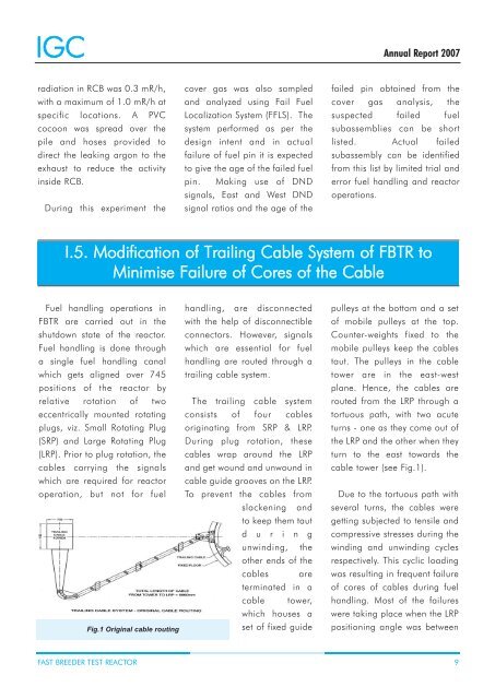
Fig.1 Original cable routing<br />
handling, are disconnected<br />
with the help of disconnectible<br />
connectors. However, signals<br />
which are essential <strong>for</strong> fuel<br />
handling are routed through a<br />
trailing cable system.<br />
The trailing cable system<br />
consists of four cables<br />
originating from SRP & LRP.<br />
During plug rotation, these<br />
cables wrap around the LRP<br />
and get wound and unwound in<br />
cable guide grooves on the LRP.<br />
To prevent the cables from<br />
slackening and<br />
to keep them taut<br />
d u r i n g<br />
unwinding, the<br />
other ends of the<br />
cables are<br />
terminated in a<br />
cable tower,<br />
which houses a<br />
set of fixed guide<br />
pulleys at the bottom and a set<br />
of mobile pulleys at the top.<br />
Counter-weights fixed to the<br />
mobile pulleys keep the cables<br />
taut. The pulleys in the cable<br />
tower are in the east-west<br />
plane. Hence, the cables are<br />
routed from the LRP through a<br />
tortuous path, with two acute<br />
turns - one as they come out of<br />
the LRP and the other when they<br />
turn to the east towards the<br />
cable tower (see Fig.1).<br />
Due to the tortuous path with<br />
several turns, the cables were<br />
getting subjected to tensile and<br />
compressive stresses during the<br />
winding and unwinding cycles<br />
respectively. This cyclic loading<br />
was resulting in frequent failure<br />
of cores of cables during fuel<br />
handling. Most of the failures<br />
were taking place when the LRP<br />
positioning angle was between<br />
FAST BREEDER TEST REACTOR 9