IGCAR : Annual Report - Indira Gandhi Centre for Atomic Research
IGCAR : Annual Report - Indira Gandhi Centre for Atomic Research
IGCAR : Annual Report - Indira Gandhi Centre for Atomic Research

Create successful ePaper yourself
Turn your PDF publications into a flip-book with our unique Google optimized e-Paper software.
IGC<br />
<strong>Annual</strong> <strong>Report</strong> 2007<br />
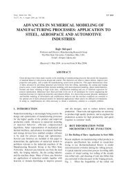
Fig.4 Peak de<strong>for</strong>mations of grid plate<br />
and stiffeners, top and bottom<br />
plates and intermediate shells<br />
of GP and CSS are modeled<br />
with plate / shell elements. The<br />
finite element mesh generated<br />
with CAST3M code, issued by<br />
CEA France is shown in Fig.2.<br />
Free vibration analysis<br />
Natural frequencies and<br />
mode shapes should be known<br />
to simulate the de<strong>for</strong>mations<br />
correctly in the subsequent<br />
impact analysis, which are<br />
determined by free vibration<br />
analysis. For this CAST3m, is<br />
used. A few important mode<br />
shapes are depicted in Fig.3.<br />
Since, upon impact, the nature<br />
of de<strong>for</strong>mation is bending of<br />
top plate, the mode depicting<br />
the bowing of top plate that<br />
occurs at 20 Hz, is the critical<br />
mode as far as impact is<br />
concerned.<br />
Impact analysis<br />
With the understanding of<br />
natural vibration behaviour and<br />
energy balance, the duration<br />
of impact and subsequently,<br />
peak <strong>for</strong>ce are defined as a<br />
triangular pulse in a classical<br />
way as follows:<br />
Velocity at time of impact<br />
vmax<br />
= √2.g.h<br />
= 2 m/s<br />
Impulse at time of impact (mv)<br />
= 1900 N-s<br />
The duration of impulse (t)<br />
= 0.025 s<br />
Peak <strong>for</strong>ce (Fmax)<br />
= 76 k N<br />
Dynamic analysis of grid plate<br />
along with core and core<br />
support structure was carried<br />
out using CAST3M code and<br />
peak de<strong>for</strong>mations and stresses<br />
are extracted. Fig.4 shows the<br />
de<strong>for</strong>mation patters at a critical<br />
instant and peak value is found<br />
to be ~ 0.1 mm and the<br />
associated Von Mises stress is<br />
found to be 20 MPa, which is<br />
local in nature. These values<br />
are found to be insignificant<br />
from the structural integrity<br />
considerations.<br />
II.5. Hardfacing of Bottom Plate of Grid Plate Assembly<br />
Grid plate of PFBR is a<br />
massive structure consisting of<br />
a two plates (top and bottom of<br />
~6.5m in diameter and large<br />
number of sleeves in which foot<br />
of the sub assemblies rest. This<br />
support structure also acts as<br />
boundary between cold and hot<br />
sodium in the reactors. Both the<br />
grid plate assembly and the<br />
core support structure are<br />
made of 316LN stainless steel<br />
and immersed in flowing<br />
sodium. Hence, there should<br />
not be any self welding between<br />
these components at their<br />
contact location. Hardfacing<br />
using Ni base hardfacing alloy<br />
(AWS Ni-Cr-B alloy) is<br />
proposed on two annular<br />
grooves machined on the<br />
bottom plate of the grid plate.<br />
These grooves are located<br />
towards the periphery of the<br />
grid plate and hence, diameters<br />
of these grroves are close to<br />
that of the grid plate itself and<br />
total length (circumference) of<br />
single harfaced deposit was<br />
close to 21 m. The component<br />
is designed in such a way that<br />
area of contact between grid<br />
plate and the core support<br />
structure is confined to these<br />
hardfaced grooves in the<br />
bottom plate.<br />
As the Ni base hardfacing<br />
alloys are highly prone to<br />
18 PROTOTYPE FAST BREEDER REACTOR