IGCAR : Annual Report - Indira Gandhi Centre for Atomic Research
IGCAR : Annual Report - Indira Gandhi Centre for Atomic Research
IGCAR : Annual Report - Indira Gandhi Centre for Atomic Research

Create successful ePaper yourself
Turn your PDF publications into a flip-book with our unique Google optimized e-Paper software.
IGC<br />
<strong>Annual</strong> <strong>Report</strong> 2007<br />
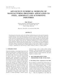
Thermal expansion (%)<br />
2.5<br />
2.0<br />
1.5<br />
1.0<br />
0.5<br />
0.0<br />
UO 2<br />
10 mol % GdO 1.5<br />
20 mol % GdO 1.5<br />
50 mol % GdO 1.5<br />
Gd 2<br />
O 3<br />
400 800 1200 1600 2000<br />
Temperature (K)<br />
Fig.2 Thermal expansion (%) as a<br />
function of temperature<br />
<strong>for</strong> UO 2 -GdO 1.5 solid solutions<br />
on these solid solutions 298-<br />
1973 K using high temperature<br />
X-ray diffraction. The thermal<br />
expansion of these solid<br />
solutions are shown in Fig.2.<br />
U-Zr metal alloys will be used<br />
as the blanket material in fast<br />
breeder reactors. Hence heat<br />
capacity data of U-Zr alloys is<br />
important. Heat capacity data<br />
of U-Zr alloys are available<br />
only <strong>for</strong> alloys with >13 at.% Zr<br />
. Heat capacity measurements<br />
were carried out on U-Zr alloy<br />
with 2, 5 and 10 wt.% Zr using<br />
heat flux differential calorimeter<br />
in the temperature range 298-<br />
800 K to generate the first<br />
experimental data which are<br />
shown in Fig.3. The measured<br />
heat capacity of pure U along<br />
C p, m<br />
(J K -1 mol -1 )<br />
45<br />
40<br />
35<br />
30<br />
25<br />
C p, m<br />
U<br />
C p, m<br />
U Hulgren et al.<br />
C p, m<br />
U Nakumura et al.<br />
C p, m<br />
U-2 wt.% Zr<br />
C p, m<br />
U-5 wt.% Zr<br />
C p, m<br />
U-10 wt.% Zr<br />
300 400 500 600 700 800 900<br />
Temperature (K)<br />
Fig.3 Heat capacity of U and U-Zr<br />
alloys<br />
with other literature values is<br />
also shown in Fig. 3 along with<br />
the literature values.<br />
IV.A.5. An Automated Facility <strong>for</strong> Charging of Fuel<br />
Micro Spheres into the Sintering Furnace<br />
Fuel preparation in the <strong>for</strong>m<br />
of micro spheres generated by<br />
the SOLGEL process is an<br />
attractive alternative to the<br />
powder route of preparation.<br />
An automated fabrication<br />
facility on the SOLGEL route<br />
has been set up in the<br />
Radiochemistry Laboratory.<br />
The fuel materials in the <strong>for</strong>m<br />
of micro spheres produced by<br />
the gelation process are first<br />
dried and are then to be<br />
loaded in a charge carrier and<br />
placed remotely into a high<br />
temperature furnace <strong>for</strong><br />
sintering.This operation is to be<br />
mechanized and per<strong>for</strong>med<br />
remotely. Towards this,an<br />
automated gripping device<br />
positionable along three coordinates,<br />
<strong>for</strong> positioning and<br />
subsequent lowering of the<br />
charge carrier into the furnace,<br />
has been developed. The<br />
device consists of an<br />
electrically actuated x-y<br />
plat<strong>for</strong>m which is mounted<br />
above the furnace as shown<br />
Fig.1. The plat<strong>for</strong>m which can<br />
be positioned in the horizontal<br />
plane, is holding an electrically<br />
operated telescopic arm fitted<br />
with a pneumatically actuated<br />
two jaw gripper.The Z axis<br />
position indicator mounted on<br />
the plat<strong>for</strong>m indicates the depth<br />
to which the gripper has been<br />
lowered. A reed sensor fixed<br />
on the end effectors is used <strong>for</strong><br />
sensing the gripping<br />
operation.The system has been<br />
commissioned with an overall<br />
positioning accuracy of 0.5<br />
mm.With no direct vision,the<br />
lowering of the charge into the<br />
furnace is assisted by a PAN-<br />
TILT camera ,as shown in the<br />
inset in Fig.1.<br />
Fig.1 Automated gripping devices<br />
<strong>for</strong> the introduction of charge<br />
carrier into the sintering furnace<br />
FUEL CYCLE 87