IGCAR : Annual Report - Indira Gandhi Centre for Atomic Research
IGCAR : Annual Report - Indira Gandhi Centre for Atomic Research
IGCAR : Annual Report - Indira Gandhi Centre for Atomic Research

Create successful ePaper yourself
Turn your PDF publications into a flip-book with our unique Google optimized e-Paper software.
IGC<br />
<strong>Annual</strong> <strong>Report</strong> 2007<br />
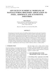
intermediate and primary<br />
sodium <strong>for</strong> the outer row. Fig. 5<br />
shows the mass flow rate of<br />
intermediate sodium from inlet<br />
Hot pool top<br />
DHX bottom<br />
Fig. 3 Temperature distribution of<br />
sodium at various elevations<br />
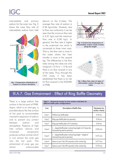
plenum to the U-tubes. The<br />
average flow rate of sodium is<br />
0.36 kg/s/tube. However, due<br />
to flow non-uni<strong>for</strong>mity it can be<br />
seen that the minimum flow rate<br />
is 0.31 kg/s and the maximum<br />
flow rate is 0.38 kg/s. In<br />
general, the flow rate is higher<br />
in the outermost row which is<br />
connected to three inner rows.<br />
That is, the flow rate is more in<br />
the tubes where the heat<br />
transfer is more in the upward<br />
leg. The differences in the flow<br />
rates among the tubes are only<br />
marginal (-13 % to + 5 %) and<br />
there is no flow reversal in any<br />
of the tubes. Thus, through this<br />
CFD study, it has been<br />
established that there is no risk<br />
<strong>for</strong> flow reversal in the SGDHRS<br />
of PFBR.<br />
Height, m<br />
4<br />
3.5<br />
3<br />
2.5<br />
2<br />
1.5<br />
1<br />
0.5<br />
0<br />
Inlet<br />
Tube - 1<br />
Tube - 2<br />
Tube - 3<br />
Tube - 4<br />
Tube - 5<br />
Tube - 6<br />
Tube - 7<br />
Tube - 8<br />
Tube - 9<br />
Tube - 10<br />
Tube - 11<br />
Tube - 12<br />
Tube - 13<br />
Tube - 14<br />
Tube - 15<br />
Row-1<br />
Row-2<br />
Row-3<br />
Row-4<br />
Row-5<br />
Baffles<br />
Outlet<br />
500 550 600 650 700 750<br />
Temperature of intermediate sodium in u-tubes, K<br />
Fig. 4 Central line temperature of<br />
intermediate sodium inside U-tubes<br />
along the length<br />
11 0.31<br />
7 0.35<br />
4 0.37 12 0.34<br />
2 0.37 8 0.36<br />
1 0.36 5 0.37 13 0.35<br />
3 0.37 9 0.37<br />
6 0.37 14 0.34<br />
10 0.36<br />
15 0.32<br />
7 0.35<br />
11 0.31<br />
3 0.37<br />
8 0.36<br />
12 0.34<br />
4 0.37<br />
1 0.36<br />
13 0.35<br />
9 0.37<br />
14 0.34<br />
2 0.37<br />
10 0.36<br />
5 0.37<br />
15 0.32<br />
6 0.37<br />
g. 5 Mass flow rates (in kg/s) of intermediate sodium through the<br />
Fig. 5 Mass flow rates (in kg/s) of<br />
intermediate sodium through the<br />
tubes<br />
III.A.7. Gas Entrainment - Effect of Ring Baffle Geometry<br />
There is a large sodium free<br />
surface in the hot pool of PFBR.<br />
Argon, which is an inert gas, is<br />
provided above the free surface<br />
of hot pool to accommodate<br />
volumetric expansion of sodium<br />
and to prevent any contact<br />
between sodium and<br />
atmosphere. Presence of high<br />
free surface velocity and<br />
immersed components<br />
produces surface vortices which<br />
in turn entrain the cover gas<br />
into the hot pool. This<br />
entrainment of cover gas can<br />
attract<br />
unfavourable<br />
Table 1 : Numerical results <strong>for</strong> free surface velocities <strong>for</strong><br />
different baffle plate configurations<br />
R&D FOR FBRs 35