- Page 1 and 2:
Technical Report TR-04-21 RD&D-Prog
- Page 3 and 4:
Preface SKB, Svensk Kärnbränsleha
- Page 5 and 6:
welding and nondestructive testing
- Page 7 and 8:
Alternative methods. SKB is followi
- Page 9 and 10:
5.5 Nondestructive testing of canis
- Page 11 and 12:
15 Fuel 163 15.1 Initial state in f
- Page 13 and 14:
18.1.10 Swelling pressure 229 18.1.
- Page 15 and 16:
Part I SKB’s programme and plan o
- Page 17 and 18:
Nuclear power plant Clab m/s Sigyn
- Page 19 and 20:
Figure 1-2. The Äspö HRL consists
- Page 21 and 22:
Figure 1-4. Interior from the Canis
- Page 23 and 24:
Siting SKB’s main alternative is
- Page 25 and 26:
Transport tunnel KBS-3V Deposition
- Page 27 and 28:
2.1 Nuclear fuel programme In Swede
- Page 29 and 30:
Encapsulation plant 2003 2004 2005
- Page 31 and 32:
2.2 LILW programme Parts of the sys
- Page 33 and 34:
environment. The barriers can also
- Page 35 and 36:
this cooperation entails that the o
- Page 37 and 38:
4 Overview - technology development
- Page 39 and 40:
4.7 Design of the deep repository T
- Page 41 and 42:
Diameter 1,050 Diameter 949 Diamete
- Page 43 and 44:
Conclusions in RD&D 2001 and its re
- Page 45 and 46:
Figure 5-3. Graphite shapes in cast
- Page 47 and 48:
Figure 5-5. Positions for test bars
- Page 49 and 50:
Programme The development project c
- Page 51 and 52:
Programme Trial fabrication of all
- Page 53 and 54:
The technology and procedures for c
- Page 55 and 56:
A method and equipment based on las
- Page 57 and 58:
Spacer plate Defect A Defect B Chan
- Page 59 and 60:
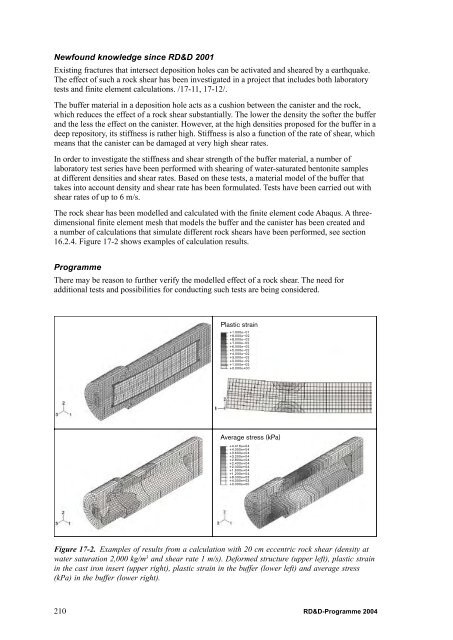
Newfound knowledge since RD&D 2001
- Page 61 and 62:
2004 2005 Process model welding met
- Page 63 and 64:
Conclusions in RD&D 2001 and its re
- Page 65 and 66:
6.2.2 The welding process In parall
- Page 67 and 68:
Figure 6-9. Lid weld L028. Section
- Page 69 and 70:
Tensile test bars have been taken o
- Page 71 and 72:
Conclusions in RD&D 2001 and its re
- Page 73 and 74:
6.3.3 The welding process The param
- Page 75 and 76:
A limitation in the evaluation of t
- Page 77 and 78:
Nondestructive testing methods such
- Page 79 and 80:
a b Through-transmission Reflection
- Page 81 and 82:
simulation program, and the body of
- Page 83 and 84:
SKB has devised a quality system fo
- Page 85 and 86:
Newfound knowledge since RD&D 2001
- Page 87 and 88:
8 Canister - encapsulation The desi
- Page 89 and 90:
Figure 8-2. Work stations in the en
- Page 91 and 92:
The filled canister transport casks
- Page 93 and 94:
Stages encapsulation plant 2003 200
- Page 95 and 96:
Figure 8-4. Possible location of a
- Page 97 and 98:
9 Transportation of encapsulated fu
- Page 99 and 100:
9.3 SKB’s transportation system -
- Page 101 and 102:
absorbs neutron radiation. The lid
- Page 103 and 104:
Applicable international and Swedis
- Page 105 and 106:
een specified yet. Since the size o
- Page 107 and 108:
• Methods exist for full-face dri
- Page 109 and 110:
Programme SKB keeps track of curren
- Page 111 and 112:
Judgement with regard to long-term
- Page 113 and 114:
Furthermore, it must not have an ad
- Page 115 and 116:
Studies of equipment will be conduc
- Page 117 and 118:
A third type of seal is intended to
- Page 119 and 120:
10.6.1 Requirements and premises In
- Page 121 and 122:
the long-term safety of the concept
- Page 123 and 124:
Newfound knowledge since RD&D 2001
- Page 125 and 126:
Conclusions in RD&D 2001 and its re
- Page 127 and 128:
11.3 Execution - stepwise design Si
- Page 129 and 130:
Programme Design step D, which incl
- Page 131 and 132:
12 Deep repository - monitoring SKB
- Page 133 and 134:
• Trigger levels for action. •
- Page 135 and 136:
Part III Safety assessment and rese
- Page 137 and 138:
As a complement to the numerical mo
- Page 139 and 140:
Table 13-2. Research on the initial
- Page 141 and 142:
13.2.4 Backfill Together with Posiv
- Page 143 and 144:
Table 13-3. Projects and experiment
- Page 145 and 146:
spent nuclear fuel. It was neverthe
- Page 147 and 148:
concepts or whose descriptions requ
- Page 149 and 150: 14.2.2 Radionuclide transport and d
- Page 151 and 152: At present, the computational time
- Page 153 and 154: Inflow Nuclides in a soluble phase
- Page 155 and 156: 15.1.2 Geometry The deep repository
- Page 157 and 158: 7 6 BWR 55 MWd/tU PWR 42 MWd/tU PWR
- Page 159 and 160: 15.1.11 Gas composition Conclusions
- Page 161 and 162: 15.2.5 Heat transport Dealt with in
- Page 163 and 164: simulating the repository environme
- Page 165 and 166: 238 U 237 Np 239 Pu Concentration,
- Page 167 and 168: The catalytic effect of uranium dio
- Page 169 and 170: oxidant consumption in the bulk sol
- Page 171 and 172: The influence of hydrogen peroxide
- Page 173 and 174: A research programme to study cast
- Page 175 and 176: Newfound knowledge since RD&D 2001
- Page 177 and 178: 16.2.3 Heat transport No new knowle
- Page 179 and 180: Programme The ongoing experiments w
- Page 181 and 182: Newfound knowledge since RD&D 2001
- Page 183 and 184: Programme Short-term tests aimed at
- Page 185 and 186: Swelling properties The buffer must
- Page 187 and 188: Newfound knowledge since RD&D 2001
- Page 189 and 190: have been performed for some ten co
- Page 191 and 192: 17.1.13 Impurity levels Bentonite i
- Page 193 and 194: out when the buffer swells, but our
- Page 195 and 196: These processes have been studied i
- Page 197 and 198: Newfound knowledge since RD&D 2001
- Page 199: • The gas injection phase will be
- Page 203 and 204: Conclusions in RD&D 2001 and its re
- Page 205 and 206: 19 9 D=205 d=175 D=172 d=170 D=168
- Page 207 and 208: • Tests of the wetting process cl
- Page 209 and 210: Newfound knowledge since RD&D 2001
- Page 211 and 212: Figure 17-4. Natural redox front in
- Page 213 and 214: These phenomena have been studied b
- Page 215 and 216: 17.2.24 Radionuclide transport - ad
- Page 217 and 218: Programme SKB does not consider sor
- Page 219 and 220: 18.1.6 Smectite content SKB, togeth
- Page 221 and 222: Programme See section 18.2.2. 18.1.
- Page 223 and 224: The wetting of the backfill from th
- Page 225 and 226: Conclusions in RD&D 2001 and its re
- Page 227 and 228: ackfill must have a compression mod
- Page 229 and 230: Programme See section 17.2.17. 18.2
- Page 231 and 232: 18.2.23 Radionuclide transport - so
- Page 233 and 234: 10 -5 I-129 Release rate (moles/yea
- Page 235 and 236: and the rock matrix, is also crucia
- Page 237 and 238: A thermal model will be constructed
- Page 239 and 240: In a continuation of the super-regi
- Page 241 and 242: A thorough overview has been done o
- Page 243 and 244: The authorities are of the opinion
- Page 245 and 246: Newfound knowledge since RD&D 2001
- Page 247 and 248: 19.2.11 Advection/mixing - groundwa
- Page 249 and 250: a so-called Markov-directed Random
- Page 251 and 252:
Diffusion measurements in the labor
- Page 253 and 254:
Uranium series analyses from clay-
- Page 255 and 256:
19.2.18 Microbial processes Conclus
- Page 257 and 258:
19.2.20 Colloid formation - colloid
- Page 259 and 260:
19.2.23 Methane ice formation Concl
- Page 261 and 262:
19.2.26 Integrated modelling - radi
- Page 263 and 264:
development that has taken place ha
- Page 265 and 266:
20.2 Review of RD&D 2001 Following
- Page 267 and 268:
work will continue, particularly in
- Page 269 and 270:
2 In Sea (mol) 3 Water Sea (mol/m 3
- Page 271 and 272:
The above work will be pursued in c
- Page 273 and 274:
certain substances, such as uranium
- Page 275 and 276:
In connection with the Safe project
- Page 277 and 278:
20.9 International work and dissemi
- Page 279 and 280:
the underlying material are current
- Page 281 and 282:
These reports describe dominant fun
- Page 283 and 284:
Glacial Permafrost Permafrost Borea
- Page 285 and 286:
Shoreline displacement has an isost
- Page 287 and 288:
The hydromechanical modellings that
- Page 289 and 290:
model that includes these factors a
- Page 291 and 292:
The salinity of the sea, inland sea
- Page 293 and 294:
• Public opinion and attitudes -
- Page 295 and 296:
Socioeconomic impact • Local deve
- Page 297 and 298:
Previously existing material is bei
- Page 299 and 300:
• The driving forces behind the d
- Page 301 and 302:
• Very effective methods for tran
- Page 303 and 304:
• A subcritical nuclear reactor w
- Page 305 and 306:
out in Cadarache, France. Hindas an
- Page 307 and 308:
Important results since 2001 includ
- Page 309 and 310:
Programme The goal of SKB’s resea
- Page 311 and 312:
Kasam says that disposal in Very De
- Page 313 and 314:
24 Decommissioning The facilities c
- Page 315 and 316:
SKB is responsible for management a
- Page 317 and 318:
25 Low- and intermediate-level wast
- Page 319 and 320:
25.2.1 Repository for short-lived L
- Page 321 and 322:
Programme Work on the design of the
- Page 323 and 324:
observation is that isosaccharinic
- Page 325 and 326:
stored so that the material can be
- Page 327 and 328:
6-4 Claesson S, 2004. Elektronstrå
- Page 329 and 330:
Chapter 14 14-1 SKB, 2004. Interim
- Page 331 and 332:
15-42 Ekeroth E, Jonsson M, 2003. O
- Page 333 and 334:
17-19 Le Bell J C, 1978. Colloid ch
- Page 335 and 336:
19-29 Hudson J (ed), 2002. Strategy
- Page 337 and 338:
19-77 Bath A, Milodowski A, Ruotsal
- Page 339 and 340:
20-19 Kautsky U (ed), 2001. The bio
- Page 341 and 342:
20-73 Blomqvist P, Jansson P-E, Esp
- Page 343 and 344:
20-119 Berggren J, Kyläkorpi L, 20
- Page 345 and 346:
23-10 NEA, 2002. Accelerator-driven
- Page 347 and 348:
SKB’s master plan Appendix A
- Page 349 and 350:
A1 Introduction A1.1 Background The
- Page 351 and 352:
generations unnecessarily. Another
- Page 353 and 354:
Encapsulation plant 2003 2004 2005
- Page 355 and 356:
facilitated by the fact that the re
- Page 357 and 358:
A2.3 System design A2.3.1 Fundament
- Page 359 and 360:
The system analyses will be largely
- Page 361 and 362:
Two safety reports will therefore b
- Page 363 and 364:
KBS-3H Basic Design Detailed engine
- Page 365 and 366:
Time horizon 2017 The current phase
- Page 367 and 368:
2003 2004 2005 2006 2007 2008 Phase
- Page 369 and 370:
In the subsequent phase, verificati
- Page 371 and 372:
The canister development work will
- Page 373 and 374:
Deep repository Year 2003 2004 2005
- Page 375 and 376:
A4.2 Site investigations Site inves
- Page 377 and 378:
Already in the feasibility study, l
- Page 379 and 380:
In step D2, the facility descriptio
- Page 381 and 382:
Table 4. Current situation and prel
- Page 383 and 384:
2003 2004 2005 2006 2007 2008 Desig
- Page 385 and 386:
Table 5. Continued. Technology issu
- Page 387 and 388:
A4.6.1 Siting factors Before priori
- Page 389 and 390:
A possible alternative scenario is
- Page 391 and 392:
of the NPPs starts, however, long-l
- Page 393 and 394:
Between now and 2008, an organizati
- Page 395 and 396:
Appendix B Abbreviations Abaqus ACL
- Page 397 and 398:
GIA Gis Goldsim Hindas HMC HPF HRL
- Page 399 and 400:
PMMA POD Posiva Prism Proper Protot
- Page 401:
ISSN 1404-0344 CM Digitaltryck AB,