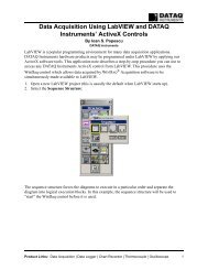
DI-770 Oscilloscope provides five virtual instruments in one
DI-770 Oscilloscope provides five virtual instruments in one
DI-770 Oscilloscope provides five virtual instruments in one

Create successful ePaper yourself
Turn your PDF publications into a flip-book with our unique Google optimized e-Paper software.
<strong>DI</strong>-<strong>770</strong> and WINDAQ/Scope Manual<br />
The b<strong>in</strong>ary format is built of records of 8 bytes large. The first two bytes are for channel 1, bytes 3 and 4 are for channel<br />
2, bytes 5 and 6 are for reference 1 and bytes 7 and 8 are for reference 2. The two bytes for each channel form a 16<br />
bits value, where 0 represents -sensitivity and 65535 represents +sensitivity.<br />
The ASCII format exists of <strong>one</strong> l<strong>in</strong>e of <strong>in</strong>formation for each sample <strong>in</strong> the record. Each l<strong>in</strong>e exists of:<br />
the sample number, related to the trigger po<strong>in</strong>t (sample number 0)<br />
the sample time, related to the trigger po<strong>in</strong>t (t=0)<br />
the voltage value for channel 1<br />
the voltage value for channel 2<br />
the voltage value for reference 1<br />
the voltage value for reference 2<br />
The items are separated by commas.<br />
The ASCII files can simply be imported <strong>in</strong> other applications, like e.g. spread sheet programs.<br />
Files <strong>in</strong> ASCII format are much larger than files <strong>in</strong> b<strong>in</strong>ary format, up to 7 times.<br />
To set the file type, enter the File menu and select the item Data file type. Choose the requested sett<strong>in</strong>g from the<br />
menu.<br />
Load<strong>in</strong>g saved measurement data from disk<br />
Previously saved waveforms can be read from disk <strong>in</strong> the oscilloscope, data logger and the spectrum analyzer. There<br />
are two ways to do this: by activat<strong>in</strong>g the Read waveform from disk item from the File menu or by click<strong>in</strong>g the Read<br />
waveform button ( ).<br />
Both ways will br<strong>in</strong>g up a load dialog <strong>in</strong> which a drive, directory and file can be selected. When a file is selected and<br />
the OK button is pressed, the waveform will be read from disk.<br />
Each waveform consists of three files: a .DAT file, a .GEG file and a .REF file. If <strong>one</strong> of these files is miss<strong>in</strong>g or the<br />
waveform data is not compatible, an error is generated.<br />
The data file type <strong>in</strong> which the data is written will be determ<strong>in</strong>ed by the software and the correct read<strong>in</strong>g functions are<br />
used.<br />
Then the data is read accord<strong>in</strong>g to the Waveform read method that is set.<br />
After read<strong>in</strong>g the data, the <strong>in</strong>strument is set to Pause (not required <strong>in</strong> the data logger) to avoid the data be<strong>in</strong>g replaced<br />
by new measured data.<br />
Note: Measurement data stored <strong>in</strong> the voltmeter can be read <strong>in</strong> the oscilloscope and the data logger.<br />
The values of display 1 of channel 1 will be placed <strong>in</strong> channel 1 of the data logger.<br />
The values of display 2 of channel 1 will be placed <strong>in</strong> Reference 1 of the data logger.<br />
The values of display 1 of channel 2 will be placed <strong>in</strong> channel 2 of the data logger.<br />
The values of display 2 of channel 2 will be placed <strong>in</strong> Reference 2 of the data logger.<br />
Sett<strong>in</strong>g the Waveform read method<br />
When a waveform is written to disk, all four channels (Ch1, Ch2, Reference 1 and Reference 2) are written to disk.<br />
There are two methods to read waveforms from disk:<br />
Read all signals <strong>in</strong> file<br />
With this method all signals that were active when the waveform was written are read. If e.g. Ch1 and Reference 2<br />
were active when the waveforms were saved, Ch1 and Reference 2 are read. the data <strong>in</strong> Ch2 and Reference 1 will<br />
rema<strong>in</strong> unchanged. Ch1 and Reference 2 will be switched on and Ch2 and Reference 1 will be switched off.<br />
Only read current displayed signals<br />
Software<br />
25