DI-770 Oscilloscope provides five virtual instruments in one
DI-770 Oscilloscope provides five virtual instruments in one
DI-770 Oscilloscope provides five virtual instruments in one

Create successful ePaper yourself
Turn your PDF publications into a flip-book with our unique Google optimized e-Paper software.
<strong>DI</strong>-<strong>770</strong> and WINDAQ/Scope Manual<br />
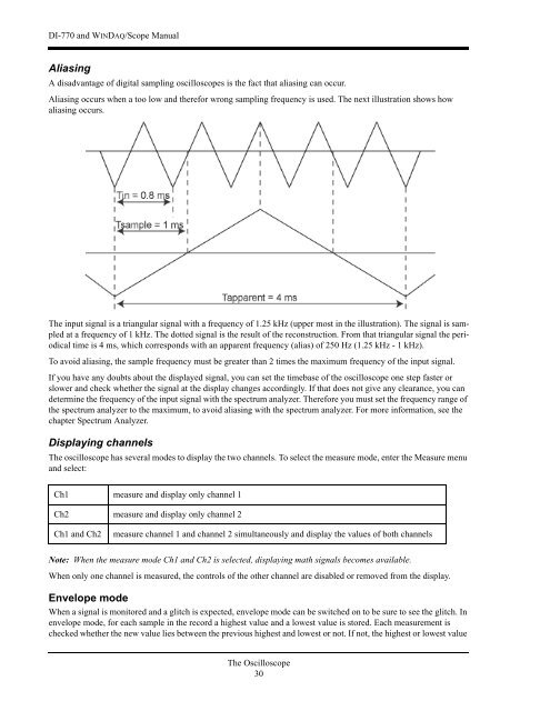
Alias<strong>in</strong>g<br />
A disadvantage of digital sampl<strong>in</strong>g oscilloscopes is the fact that alias<strong>in</strong>g can occur.<br />
Alias<strong>in</strong>g occurs when a too low and therefor wrong sampl<strong>in</strong>g frequency is used. The next illustration shows how<br />
alias<strong>in</strong>g occurs.<br />
The <strong>in</strong>put signal is a triangular signal with a frequency of 1.25 kHz (upper most <strong>in</strong> the illustration). The signal is sampled<br />
at a frequency of 1 kHz. The dotted signal is the result of the reconstruction. From that triangular signal the periodical<br />
time is 4 ms, which corresponds with an apparent frequency (alias) of 250 Hz (1.25 kHz - 1 kHz).<br />
To avoid alias<strong>in</strong>g, the sample frequency must be greater than 2 times the maximum frequency of the <strong>in</strong>put signal.<br />
If you have any doubts about the displayed signal, you can set the timebase of the oscilloscope <strong>one</strong> step faster or<br />
slower and check whether the signal at the display changes accord<strong>in</strong>gly. If that does not give any clearance, you can<br />
determ<strong>in</strong>e the frequency of the <strong>in</strong>put signal with the spectrum analyzer. Therefore you must set the frequency range of<br />
the spectrum analyzer to the maximum, to avoid alias<strong>in</strong>g with the spectrum analyzer. For more <strong>in</strong>formation, see the<br />
chapter Spectrum Analyzer.<br />
Display<strong>in</strong>g channels<br />
The oscilloscope has several modes to display the two channels. To select the measure mode, enter the Measure menu<br />
and select:<br />
Ch1 measure and display only channel 1<br />
Ch2 measure and display only channel 2<br />
Ch1 and Ch2<br />
measure channel 1 and channel 2 simultaneously and display the values of both channels<br />
Note: When the measure mode Ch1 and Ch2 is selected, display<strong>in</strong>g math signals becomes available.<br />
When only <strong>one</strong> channel is measured, the controls of the other channel are disabled or removed from the display.<br />
Envelope mode<br />
When a signal is monitored and a glitch is expected, envelope mode can be switched on to be sure to see the glitch. In<br />
envelope mode, for each sample <strong>in</strong> the record a highest value and a lowest value is stored. Each measurement is<br />
checked whether the new value lies between the previous highest and lowest or not. If not, the highest or lowest value<br />
The <strong>Oscilloscope</strong><br />
30