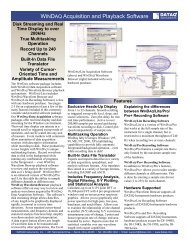
DI-770 Oscilloscope provides five virtual instruments in one
DI-770 Oscilloscope provides five virtual instruments in one
DI-770 Oscilloscope provides five virtual instruments in one

You also want an ePaper? Increase the reach of your titles
YUMPU automatically turns print PDFs into web optimized ePapers that Google loves.
<strong>DI</strong>-<strong>770</strong> and WINDAQ/Scope Manual<br />
frequency <strong>in</strong> the spectrum analyzer sets the start frequency of the sweep. The highest visible frequency <strong>in</strong> the spectrum<br />
analyzer sets the stop frequency of the sweep. This is limited to the maximum range of the function generator.<br />
The frequency step size is determ<strong>in</strong>ed by the frequency range of the spectrum analyzer, divided by the number of b<strong>in</strong>s<br />
<strong>in</strong> the spectrum. When a sweep is active and a sett<strong>in</strong>g <strong>in</strong> the spectrum analyzer is changed, the sweep parameters will<br />
change accord<strong>in</strong>gly.<br />
At each step, the frequency of the generator will be set to a value that falls exactly <strong>in</strong> <strong>one</strong> s<strong>in</strong>gle b<strong>in</strong>, therefor no calculation<br />
errors occur and no w<strong>in</strong>dow is required.<br />
The sett<strong>in</strong>g Manual requires that all sett<strong>in</strong>gs are set by the user. The start and stop frequency can be set freely. The frequency<br />
axis of the spectrum analyzer will be set accord<strong>in</strong>gly, so only the range that is sweeped will be visible.<br />
The frequency step size can be determ<strong>in</strong>ed from the spectrum length. With each step a frequency will be set that generates<br />
no calculation errors. It's also possible to set the step size manually, but that will probably do generate calculation<br />
errors <strong>in</strong> the FFT.<br />
H<strong>in</strong>t: For easy creat<strong>in</strong>g frequency response characteristics, set the measure mode of the spectrum analyzer to Measure<br />
maximum values and switch off autorang<strong>in</strong>g for the channels<br />
After sett<strong>in</strong>g the sweep parameters, the sweep function can be switched on us<strong>in</strong>g the on/off button. Dur<strong>in</strong>g the sweep,<br />
the frequency readout <strong>in</strong> the display will follow the output frequency.<br />
Note: When the sweep function is used to determ<strong>in</strong>e frequency response characteristics, be certa<strong>in</strong> to set the signal<br />
shape to S<strong>in</strong>e.<br />
Generat<strong>in</strong>g a previous measured signal from a file<br />
It is possible to generate previously measured signals with the function generator, provided of course that the amplitude<br />
and frequency of the signal are with<strong>in</strong> the specs of the generator.<br />
Measur<strong>in</strong>g and stor<strong>in</strong>g a signal<br />
The function generator has two possibilities to generate previous measured signals. It can either use the DDS mode or<br />
it can use a l<strong>in</strong>ear mode.<br />
In the DDS mode, a waveform of 1024 po<strong>in</strong>ts is used to generate the signal. Due to the DDS technique, very accurate<br />
output signal frequencies can be obta<strong>in</strong>ed.<br />
In l<strong>in</strong>ear mode, a waveform of 64K po<strong>in</strong>ts is used. The sample clock of the generator can be set to a number of sett<strong>in</strong>gs,<br />
<strong>in</strong> order to obta<strong>in</strong> different output frequencies. The number of sett<strong>in</strong>gs is limited. When a stored waveform is<br />
used that is smaller than 64K po<strong>in</strong>ts, the rema<strong>in</strong><strong>in</strong>g po<strong>in</strong>ts are filled with a 0 volt value.<br />
A signal that is measured, stored and later generated, has to meet certa<strong>in</strong> po<strong>in</strong>ts, <strong>in</strong> order to be usable.<br />
• The signal has to be measured <strong>in</strong> channel 1 of the scope.<br />
• For DDS mode, the record length of the scope has to be set to 1024 po<strong>in</strong>ts, for l<strong>in</strong>ear mode to any required<br />
length, but 64K is preferred.<br />
• If possible, the sampl<strong>in</strong>g frequency of the scope has to be set <strong>in</strong> such a way that exactly 1 period of the signal is<br />
captured <strong>in</strong> the 1024 po<strong>in</strong>ts or 64K po<strong>in</strong>ts.<br />
After the signal is measured, it can be saved to disk us<strong>in</strong>g Save waveform... from the File-menu.<br />
Sett<strong>in</strong>g the function generator<br />
At the left hand side of the display <strong>in</strong> the generator, a number of signal shape buttons are located, <strong>one</strong> of them is<br />
named File. With this button a signal from a file can be selected and loaded <strong>in</strong>to the generator.<br />
Press<strong>in</strong>g this button will pop up a file selection dialog <strong>in</strong> which the proper waveform file can be selected.<br />
After read<strong>in</strong>g the signal, the amplitude and frequency of the signal can be adjusted us<strong>in</strong>g the proper controls.<br />
The Function Generator<br />
74