DI-770 Oscilloscope provides five virtual instruments in one
DI-770 Oscilloscope provides five virtual instruments in one
DI-770 Oscilloscope provides five virtual instruments in one

Create successful ePaper yourself
Turn your PDF publications into a flip-book with our unique Google optimized e-Paper software.
<strong>DI</strong>-<strong>770</strong> and WINDAQ/Scope Manual<br />
To change the record view offset, place the mouse po<strong>in</strong>ter anywhere on the slider, except on the left hand side or the<br />
right hand side. The mouse po<strong>in</strong>ter will not change shape. Press the left mouse button and drag the slider to the position<br />
you want. The record view offset will be adjusted and the signal <strong>in</strong> the display changes accord<strong>in</strong>gly.<br />
When the small buttons are clicked, the record view offset is <strong>in</strong>creased or decreased by 1 sample. When the mouse is<br />
clicked with<strong>in</strong> the scroll bar but outside the slider, the record view offset is <strong>in</strong>creased or decreased by 5 samples,<br />
depend<strong>in</strong>g on which side of the scroll bar is clicked. When the mouse button is kept pressed, an auto repeat function<br />
is activated.<br />
Trigger<strong>in</strong>g<br />
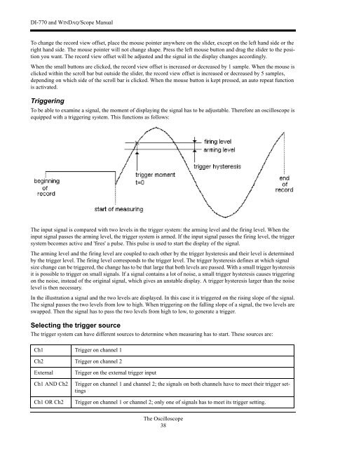
To be able to exam<strong>in</strong>e a signal, the moment of display<strong>in</strong>g the signal has to be adjustable. Therefore an oscilloscope is<br />
equipped with a trigger<strong>in</strong>g system. This functions as follows:<br />
The <strong>in</strong>put signal is compared with two levels <strong>in</strong> the trigger system: the arm<strong>in</strong>g level and the fir<strong>in</strong>g level. When the<br />
<strong>in</strong>put signal passes the arm<strong>in</strong>g level, the trigger system is armed. If the <strong>in</strong>put signal passes the fir<strong>in</strong>g level, the trigger<br />
system becomes active and 'fires' a pulse. This pulse is used to start the display of the signal.<br />
The arm<strong>in</strong>g level and the fir<strong>in</strong>g level are coupled to each other by the trigger hysteresis and their level is determ<strong>in</strong>ed<br />
by the trigger level. The fir<strong>in</strong>g level corresponds to the trigger level. The trigger hysteresis def<strong>in</strong>es at which signal<br />
size change can be triggered, the change has to be that large that both levels are passed. With a small trigger hysteresis<br />
it is possible to trigger on small signals. If a signal conta<strong>in</strong>s a lot of noise, a small trigger hysteresis causes trigger<strong>in</strong>g<br />
on the noise, <strong>in</strong>stead of the orig<strong>in</strong>al signal, which gives an unstable display. A trigger hysteresis larger than the noise<br />
level is then necessary.<br />
In the illustration a signal and the two levels are displayed. In this case it is triggered on the ris<strong>in</strong>g slope of the signal.<br />
The signal passes the two levels from low to high. When trigger<strong>in</strong>g on the fall<strong>in</strong>g slope of a signal, the two levels are<br />
swapped. Then the signal has to pass the two levels from high to low, to generate a trigger.<br />
Select<strong>in</strong>g the trigger source<br />
The trigger system can have different sources to determ<strong>in</strong>e when measur<strong>in</strong>g has to start. These sources are:<br />
Ch1 Trigger on channel 1<br />
Ch2 Trigger on channel 2<br />
External<br />
Ch1 AND Ch2<br />
Ch1 OR Ch2<br />
Trigger on the external trigger <strong>in</strong>put<br />
Trigger on channel 1 and channel 2; the signals on both channels have to meet their trigger sett<strong>in</strong>gs<br />
Trigger on channel 1 or channel 2; only <strong>one</strong> of signals has to meet its trigger sett<strong>in</strong>g.<br />
The <strong>Oscilloscope</strong><br />
38