
Create successful ePaper yourself
Turn your PDF publications into a flip-book with our unique Google optimized e-Paper software.
5.7. DEVICES 105<br />
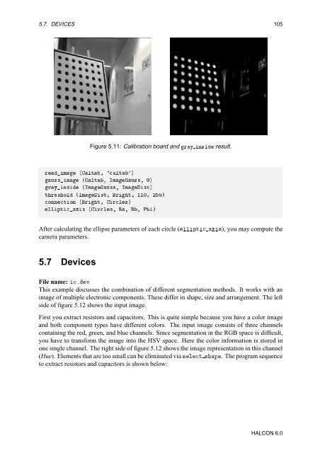
Figure 5.11: Calibration board and ÖÝ Ò× result.<br />
ÖÑ ´Ðظ ³Ðسµ<br />
Ù××Ñ ´Ðظ ÁÑÙ×׸ µ<br />
ÖÝÒ× ´ÁÑÙ×׸ ÁÑ×ص<br />
ØÖ×ÓÐ ´ÁÑ×ظ Öظ ½½¼¸ ¾µ<br />
ÓÒÒØÓÒ ´Öظ ÖÐ×µ<br />
ÐÐÔØÜ× ´ÖÐ׸ ʸ ʸ ȵ<br />
After calculating the ellipse parameters of each circle (ÐÐÔØ Ü×), you may compute the<br />
camera parameters.<br />
5.7 Devices<br />
File name: ºÚ<br />
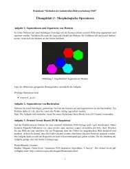
This example discusses the combination of different segmentation methods. It works with an<br />
image of multiple electronic components. These differ in shape, size and arrangement. The left<br />
side of figure 5.12 shows the input image.<br />
First you extract resistors and capacitors. This is quite simple because you have a color image<br />
and both component types have different colors. The input image consists of three channels<br />
containing the red, green, and blue channels. Since segmentation in the RGB space is difficult,<br />
you have to transform the image into the HSV space. Here the color information is stored in<br />
one single channel. The right side of figure 5.12 shows the image representation in this channel<br />
(Hue). Elements that are too small can be eliminated via ×ÐØ ×Ô. The program sequence<br />
to extract resistors and capacitors is shown below:<br />
HALCON 6.0