iaea human health series publications - SEDIM
iaea human health series publications - SEDIM
iaea human health series publications - SEDIM
- No tags were found...

Create successful ePaper yourself
Turn your PDF publications into a flip-book with our unique Google optimized e-Paper software.
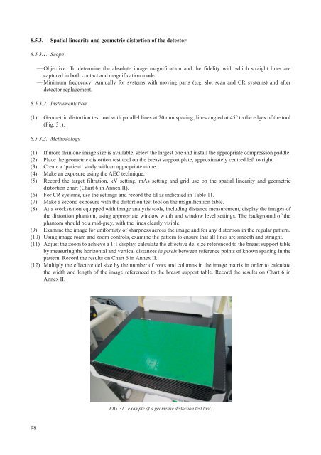
8.5.3. Spatial linearity and geometric distortion of the detector8.5.3.1. Scope— Objective: To determine the absolute image magnification and the fidelity with which straight lines arecaptured in both contact and magnification mode.— Minimum frequency: Annually for systems with moving parts (e.g. slot scan and CR systems) and afterdetector replacement.8.5.3.2. Instrumentation(1) Geometric distortion test tool with parallel lines at 20 mm spacing, lines angled at 45° to the edges of the tool(Fig. 31).8.5.3.3. Methodology(1) If more than one image size is available, select the largest one and install the appropriate compression paddle.(2) Place the geometric distortion test tool on the breast support plate, approximately centred left to right.(3) Create a ‘patient’ study with an appropriate name.(4) Make an exposure using the AEC technique.(5) Record the target filtration, kV setting, mAs setting and grid use on the spatial linearity and geometricdistortion chart (Chart 6 in Annex II).(6) For CR systems, use the settings and record the EI as indicated in Table 11.(7) Make a second exposure with the distortion test tool on the magnification table.(8) At a workstation equipped with image analysis tools, including distance measurement, display the images ofthe distortion phantom, using appropriate window width and window level settings. The background of thephantom should be a mid-grey, with the lines clearly visible.(9) Examine the image for uniformity of sharpness across the image and for any distortion in the regular pattern.(10) Using image roam and zoom controls, examine the pattern to ensure that all lines are smooth and straight.(11) Adjust the zoom to achieve a 1:1 display, calculate the effective del size referenced to the breast support tableby measuring the horizontal and vertical distances in pixels between reference points of known spacing in thepattern. Record the results on Chart 6 in Annex II.(12) Multiply the effective del size by the number of rows and columns in the image matrix in order to calculatethe width and length of the image referenced to the breast support table. Record the results on Chart 6 inAnnex II.FIG. 31. Example of a geometric distortion test tool.98