iaea human health series publications - SEDIM
iaea human health series publications - SEDIM
iaea human health series publications - SEDIM
- No tags were found...
You also want an ePaper? Increase the reach of your titles
YUMPU automatically turns print PDFs into web optimized ePapers that Google loves.
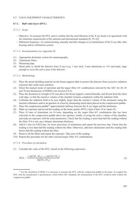
8.7. X RAY EQUIPMENT CHARACTERISTICS8.7.1. Half value layer (HVL)8.7.1.1. Scope— Objective: To measure the HVL and to confirm that the total filtration of the X ray beam is in agreement withthe minimum requirements of the national and international standards [8, 59–62].— Minimum frequency: At commissioning, annually and after changes to or maintenance of the X ray tube, tubehousing and/or collimation system.8.7.1.2. Instrumentation (see Appendix II)(1) Appropriate dosimeter system for mammography.(2) Aluminium filters.(3) Measuring tape.(4) Metal plate to shield the detector from X rays (e.g. 1 mm steel, 5 mm aluminium or >0.1 mm lead), largeenough to cover the active area of the detector.8.7.1.3. Methodology(1) Place the metal shielding material on the breast support table to protect the detector from excessive radiationexposure that could cause artefacts.(2) Select the manual mode of operation and the target–filter–kV combinations selected by the AEC for 20, 45and 70 mm thicknesses of PMMA (see Section 8.4.2).(3) Place the dosimeter at a height of 45 mm above the breast support, centred laterally, and 40 mm from the chestwall edge, so that the sensitive volume of the chamber remains completely within the radiation field.(4) Collimate the radiation field to be just slightly larger than the sensitive volume of the dosimeter using theinternal collimators and/or an aperture in a heavily attenuating metal sheet placed on the compression paddle.(5) Place the compression paddle 22 approximately halfway between the X ray target and the dosimeter.(6) Make an exposure and record the reading on the beam quality (HVL) chart (Chart 10 in Annex II).(7) Place 0.3 mm of aluminium (or 0.4 mm, depending on the target–filter–kV combination that has beenselected) on the compression paddle above the aperture, totally covering the active volume of the chamber,and make an exposure with the same parameters. Check that the reading is more than half the reading withoutthe filter. If it is not, use a thinner aluminium thickness.(8) Add 0.1 mm (or 0.025 mm, for more precision) of aluminium and repeat the previous step. Check that thereading is less than half the reading without the filter. Otherwise, add more aluminium until the reading fallsbelow half the reading without the filter.(9) Remove all the filters and repeat the exposure. Take note of the reading.(10) Repeat this procedure for the other selected target–filter–kV combinations.8.7.1.4. Procedure of calculation(1) Calculate the value of the HVL, based on the following expression:HVL =t ln[ 2M / M ] - t ln[ 2M2/M ]1 1 0 2 0ln[ 2M/ M ]1 2(3)22For the calculation of MGD, it is necessary to measure the HVL with the compression paddle in the beam. To compare theHVL with the manufacturer’s specifications, which follow IEC standards, the measurement of the HVL would be done without thecompression paddle.109


