iaea human health series publications - SEDIM
iaea human health series publications - SEDIM
iaea human health series publications - SEDIM
- No tags were found...

Create successful ePaper yourself
Turn your PDF publications into a flip-book with our unique Google optimized e-Paper software.
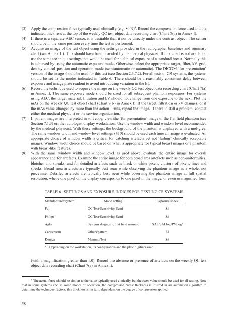
(3) Apply the compression force typically used clinically (e.g. 80 N) 4 . Record the compression force used and theindicated thickness at the top of the weekly QC test object data recording chart (Chart 7(a) in Annex I).(4) If there is a separate AEC sensor, it is desirable that it not be directly under the contrast object. The sensorshould be in the same position every time the test is performed.(5) Acquire an image of the test object using the settings provided in the radiographer baselines and summarychart (see Annex II). This should have been provided by the medical physicist. If this chart is not available,use the same technique settings that would be used for a clinical exposure of a standard breast. Normally thisis achieved by using the automatic exposure mode. Otherwise, select the appropriate target, filter, kV, grid,density control position and operation mode (semiautomatic or automatic). The DICOM ‘for presentation’version of the image should be used for this test (see Section 2.3.7.2). For all tests of CR systems, the systemsshould be set to the modes indicated in Table 6. There should be a reasonably consistent delay betweenexposure and image plate readout to avoid introducing variation in the EI.(6) Record the technique used to acquire the image on the weekly QC test object data recording chart (Chart 7(a)in Annex I). The same exposure mode should be used for all subsequent phantom exposures. For systemsusing AEC, the target material, filtration and kV should not change from one exposure to the next. Plot themAs on the weekly QC test object chart (Chart 7(b) in Annex I). If the target, filtration or kV changes, or ifthe mAs value changes by more than the action limits, repeat the image. If there is still a problem, contacteither the medical physicist or the service organization.(7) If patient images are interpreted in soft copy, view the ‘for presentation’ image of the flat field phantom (seeSection 7.1.3) on the radiologist display workstation. Use the window width and window level recommendedby the medical physicist. With these settings, the background of the phantom is displayed with a mid-grey.The same window width and window level settings (±10) should be used each time an image is evaluated. Anappropriate choice of window width is critical for catching artefacts yet not ‘failing’ clinically acceptableimages. Window width choice should be based on what is appropriate for typical breast images or a phantomwith breast-like features.(8) With the same window width and window level as used above, evaluate the entire image for overallappearance and for artefacts. Examine the entire image for both broad area artefacts such as non-uniformities,blotches and streaks, and for detailed artefacts such as black or white pixels, clusters of pixels, lines andspecks. Broad area artefacts are typically best seen while observing the phantom image as a whole, notpiecewise. Detailed artefacts are typically best seen while observing the phantom image at full spatialresolution, where one pixel on the display corresponds to one pixel in the image, or even in magnified formTABLE 6. SETTINGS AND EXPOSURE INDICES FOR TESTING CR SYSTEMSManufacturer/system Mode setting Exposure indexFuji QC Test/Sensitivity Semi S#Philips QC Test/Sensitivity Semi S#Agfa Systems diagnostic/flat field mammo SAL/SALlog/PVIlog aCarestream Others/pattern EIKonica Mammo/Test S#aDepending on the workstation, its configuration and the plate digitizer used.(with a magnification greater than 1.0). Record the absence or presence of artefacts on the weekly QC testobject data recording chart (Chart 7(a) in Annex I).4The actual force should be similar to the value typically used clinically, but the same value should be used for all testing. Notethat in some systems and in some modes of operation, the compressed breast thickness is utilized in an automated algorithm todetermine the technique factors; this thickness is, in turn, dependent on the degree of compression applied.58