iaea human health series publications - SEDIM
iaea human health series publications - SEDIM
iaea human health series publications - SEDIM
- No tags were found...
You also want an ePaper? Increase the reach of your titles
YUMPU automatically turns print PDFs into web optimized ePapers that Google loves.
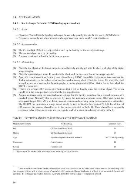
8.4. AEC EVALUATION8.4.1. Site technique factors for SDNR (radiographer baseline)8.4.1.1. Scope— Objective: To establish the baseline technique factors to be used by the site for the weekly SDNR check.— Frequency: Annually and when updates or changes have been made to AEC control software.8.4.1.2. Instrumentation(1) The 45 mm thick PMMA test object that is used by the facility for the weekly test image.(2) The contrast object used by the facility.(3) A spacer is not used unless the facility uses a spacer.8.4.1.3. Methodology(1) Place the test object on the breast support centred laterally and aligned with the chest wall edge of the digitalimage receptor.(2) Place the contrast object about 40 mm from the chest wall, on the centre line of the image detector.(3) Apply the compression force typically used clinically (e.g. 80 N) 9 . Record the compression force used and thethickness indicated on the radiographer baselines and summary chart (Chart 3 in Annex II), where they willbe used to provide a baseline for the radiographer’s routine phantom test (Chart 7(a) in Annex I) in which theSDNR is measured.(4) If there is a separate AEC sensor, it is desirable that it not be directly under the contrast object. The sensorshould be in the same position every time the test is performed.(5) Acquire an image using the same technique settings that the facility would use for a clinical exposure of astandard breast. Normally this is achieved by using the automatic exposure mode. Otherwise, select theappropriate target, filter, kV, grid, density control position and operating mode (semiautomatic or automatic).The DICOM ‘for presentation’ image format should be used for this test (see Section 2.3.7.2). For all tests ofCR systems, the systems should be set to the modes indicated in Table 11. There should be a reasonablyconsistent delay between exposure and image plate readout to avoid introducing variation in the EI.TABLE 11. SETTINGS AND EXPOSURE INDICES FOR TESTING CR SYSTEMSManufacturer/system Mode setting Exposure indexFuji QC Test/Sensitivity Semi S#Philips QC Test/Sensitivity Semi S#Agfa Systems diagnostic/flat field mammo SAL/SALlog/PVIlog aCarestream Others/pattern EIKonica Mammo/Test S#aDepending on the workstation, its configuration and the plate digitizer used.9The actual force should be similar to the typical value used clinically, but the same value should be used for all testing. Notethat in some systems and in some modes of operation, the compressed breast thickness is utilized in an automated algorithm todetermine the technique factors; this thickness is, in turn, dependent on the degree of compression applied.86


