iaea human health series publications - SEDIM
iaea human health series publications - SEDIM
iaea human health series publications - SEDIM
- No tags were found...

Create successful ePaper yourself
Turn your PDF publications into a flip-book with our unique Google optimized e-Paper software.
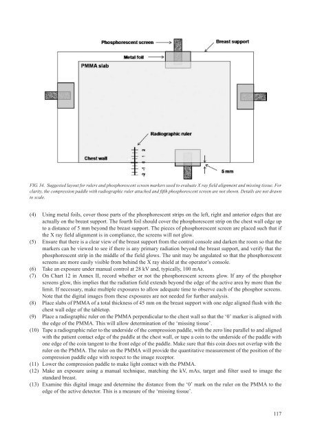
FIG. 34. Suggested layout for rulers and phosphorescent screen markers used to evaluate X ray field alignment and missing tissue. Forclarity, the compression paddle with radiographic ruler attached and fifth phosphorescent screen are not shown. Details are not drawnto scale.(4) Using metal foils, cover those parts of the phosphorescent strips on the left, right and anterior edges that areactually on the breast support. The fourth foil should cover the phosphorescent strip on the chest wall edge upto a distance of 5 mm beyond the breast support. The pieces of phosphorescent screen are placed such that ifthe X ray field alignment is in compliance, the screens will not glow.(5) Ensure that there is a clear view of the breast support from the control console and darken the room so that themarkers can be viewed to see if there is any primary radiation beyond the breast support, and verify that thephosphorescent strip in the middle of the field glows. The unit may be angulated so that the phosphorescentscreens are more easily visible from behind the X ray shield at the operator’s console.(6) Take an exposure under manual control at 28 kV and, typically, 100 mAs.(7) On Chart 12 in Annex II, record whether or not the phosphorescent screens glow. If any of the phosphorscreens glow, this implies that the radiation field extends beyond the edge of the active area by more than thelimit. If necessary, make multiple exposures to allow adequate time to observe each of the phosphor screens.Note that the digital images from these exposures are not needed for further analysis.(8) Place slabs of PMMA of a total thickness of 45 mm on the breast support with one edge aligned flush with thechest wall edge of the tabletop.(9) Place a radiographic ruler on the PMMA perpendicular to the chest wall so that the ‘0’ marker is aligned withthe edge of the PMMA. This will allow determination of the ‘missing tissue’.(10) Tape a radiographic ruler to the underside of the compression paddle, with the zero line parallel to and alignedwith the patient contact edge of the paddle at the chest wall, or tape a coin to the underside of the paddle withone edge of the coin tangent to the front edge of the paddle. Make sure that this coin does not overlap with theruler on the PMMA. The ruler on the PMMA will provide the quantitative measurement of the position of thecompression paddle edge with respect to the image receptor.(11) Lower the compression paddle to make light contact with the PMMA.(12) Make an exposure using a manual technique, matching the kV, mAs, target and filter used to image thestandard breast.(13) Examine this digital image and determine the distance from the ‘0’ mark on the ruler on the PMMA to theedge of the active detector. This is a measure of the ‘missing tissue’.117