

The mechanical effects of short-circuit currents in - Montefiore
The mechanical effects of short-circuit currents in - Montefiore
The mechanical effects of short-circuit currents in - Montefiore

Create successful ePaper yourself
Turn your PDF publications into a flip-book with our unique Google optimized e-Paper software.
)<br />
a)<br />
σF σ0,2 σ0,01 σ<br />
ε 0,01 ε 0,2<br />
c)<br />
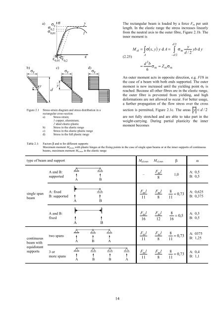
Figure 2.1 Stress-stra<strong>in</strong> diagram and stress distribution <strong>in</strong> a<br />
rectangular cross-section<br />
a) Stress-stra<strong>in</strong>;<br />
1 copper, alum<strong>in</strong>ium;<br />
2 ideal elastic-plastic<br />
b) Stress <strong>in</strong> the elastic range<br />
c) Stress <strong>in</strong> the elastic-plastic range<br />
d) Stress <strong>in</strong> the full plastic range<br />
2<br />
1<br />
ε<br />
d)<br />
14<br />
<strong>The</strong> rectangular beam is loaded by a force Fm per unit<br />
length. In the elastic range the stress <strong>in</strong>creases l<strong>in</strong>early<br />
from the neutral axis to the outer fibre, Figure 2.1b. <strong>The</strong><br />
<strong>in</strong>ner moment is<br />
(2.25)<br />
M<br />
el<br />
2<br />
( x,<br />
y)<br />
d b<br />
= σ<br />
6<br />
m<br />
m<br />
m<br />
d/<br />
2<br />
= ∫σydA= ∫<br />
A<br />
= Z<br />
σ<br />
−d/<br />
2<br />
σ<br />
m<br />
y<br />
d / 2<br />
yb d y<br />
An outer moment acts <strong>in</strong> opposite direction, e.g. Fl/8 <strong>in</strong><br />
the case <strong>of</strong> a beam with both ends supported. <strong>The</strong> outer<br />
moment is now <strong>in</strong>creased until the yield<strong>in</strong>g po<strong>in</strong>t σF is<br />
reached. Because all other fibres are <strong>in</strong> the elastic range,<br />
the outer fibre is prevented from yield<strong>in</strong>g, and high<br />
deformations are not allowed to occur. For better usage,<br />
a further propagation <strong>of</strong> the flow stress over the cross<br />
section is permitted, Figure 2.1c. <strong>The</strong> areas y < d / 2<br />
are not fully stretched and are able to take part <strong>in</strong> the<br />
weight-carry<strong>in</strong>g. Dur<strong>in</strong>g partial plasticity the <strong>in</strong>ner<br />
moment becomes<br />
Table 2.1: Factors β and α for different supports<br />
Maximum moment Mpl,max with plastic h<strong>in</strong>ges at the fix<strong>in</strong>g po<strong>in</strong>ts <strong>in</strong> the case <strong>of</strong> s<strong>in</strong>gle span beams or at the <strong>in</strong>ner supports <strong>of</strong> cont<strong>in</strong>uous<br />
beams, maximum moment Mel,max <strong>in</strong> the elastic range<br />
type <strong>of</strong> beam and support Mpl,max Mel,max β α<br />
s<strong>in</strong>gle span<br />
beam<br />
A and B:<br />
supported<br />
A: fixed<br />
B: supported<br />
A and B:<br />
fixed<br />
two spans<br />
cont<strong>in</strong>uous<br />
beam with<br />
equidistant<br />
supports 3 or<br />
more spans<br />
–<br />
m<br />
11<br />
l F<br />
m<br />
16<br />
l F<br />
m<br />
11<br />
l F<br />
m<br />
11<br />
l F<br />
m<br />
8<br />
l F 1,0<br />
A: 0,5<br />
B: 0,5<br />
m<br />
8<br />
l F 8 A: 0,625<br />
= 0,<br />
73<br />
11 B: 0,375<br />
m<br />
12<br />
l F 8 A: 0,5<br />
= 0,<br />
5<br />
16 B: 0,5<br />
m<br />
8<br />
l F 8 A: 0375<br />
= 0,<br />
73<br />
11 B: 1,25<br />
m<br />
8<br />
l F 8 A: 0,4<br />
= 0,<br />
73<br />
11 B: 1,1


