

The mechanical effects of short-circuit currents in - Montefiore
The mechanical effects of short-circuit currents in - Montefiore
The mechanical effects of short-circuit currents in - Montefiore

Create successful ePaper yourself
Turn your PDF publications into a flip-book with our unique Google optimized e-Paper software.
(2.26)<br />
M<br />
el-pl<br />
⎡ y<br />
d/<br />
2<br />
y<br />
= 2⎢<br />
σ yb y + σ<br />
⎢∫<br />
F d<br />
y ∫<br />
⎣0<br />
y<br />
= σ<br />
F<br />
⎡<br />
d<br />
⎢<br />
⎛ ⎞<br />
⎜ ⎟<br />
⎢<br />
⎣<br />
⎝ 2 ⎠<br />
2<br />
2<br />
y<br />
⎤<br />
− ⎥ b<br />
3 ⎥<br />
⎦<br />
F<br />
⎤<br />
yb d y⎥<br />
⎥<br />
⎦<br />
When y = 0 the flow stress is <strong>in</strong> the complete cross<br />
section, Figure 2.1d. With a permanent lengthen<strong>in</strong>g <strong>in</strong><br />
the outer fibre <strong>of</strong> ε0,2 = 0,2 %, an outer moment MTr acts<br />
which is called realistic ultimate load. It is equal to the<br />
<strong>in</strong>ner moment Mel-pl accord<strong>in</strong>g to equation (2.26):<br />
(2.27)<br />
M<br />
Tr<br />
= M<br />
el-pl<br />
= 1,<br />
5Z<br />
m<br />
( y = 0)<br />
σ<br />
0,2<br />
m<br />
2<br />
d b<br />
= σ<br />
4<br />
= qZ σ<br />
In contrast to the pure elastic limit the outer moment can<br />
be <strong>in</strong>creased about 50 %. <strong>The</strong>n the load capacity is<br />
exhausted. <strong>The</strong> perfect plastic factor is q = 1,5 for<br />
rectangular pr<strong>of</strong>iles. With other pr<strong>of</strong>iles factor q<br />
deviates and is given <strong>in</strong> Table 2.2 [Ref 21, Ref 22].<br />
<strong>The</strong> permanent deformation <strong>of</strong> ε0,2 = 0,2 % is equivalent<br />
to the yield<strong>in</strong>g po<strong>in</strong>t Rp0,2. <strong>The</strong> maximum value <strong>of</strong> the<br />
stresses σm respectively σtot shall not be greater than<br />
given by the realistic ultimate load <strong>in</strong> equation (2.27):<br />
0,2<br />
0,2<br />
(2.28) σ m ≤ qRp0,2<br />
resp. σ tot ≤ qRp0,2<br />
It is recommended not to exceed the yield<strong>in</strong>g po<strong>in</strong>t <strong>in</strong><br />
the case <strong>of</strong> sub-conductor stress σs <strong>in</strong> order to hold the<br />
distance between the sub-conductors nearly constant:<br />
R ≤<br />
(2.29) s p0,2<br />
σ<br />
If ranges for the value Rp0,2 accord<strong>in</strong>g to the yield<strong>in</strong>g<br />
po<strong>in</strong>t are available, the m<strong>in</strong>imum limit Rp0,2 should be<br />
used <strong>in</strong> equations (2.28) and (2.29) to get a permanent<br />
deformation which is not too large.<br />
To regard the plasticity under consideration <strong>of</strong> the<br />
transition from complete to partial fixation a higher<br />
load<strong>in</strong>g is possible <strong>in</strong> contrast to the calculation only <strong>in</strong><br />
the elastic range, if a little permanent deformation is<br />
permitted. In the case <strong>of</strong> beams fixed/ fixed it becomes<br />
4/3·1,5 = 2 which agrees with the measured value <strong>in</strong><br />
equation (2.22). In substations, normally tubes with s/D<br />
= 0,02 ... 0,3 over two or more spans are used. In this<br />
case the load<strong>in</strong>g can be <strong>in</strong>creased by the factor 1,8 ...2,3.<br />
15<br />
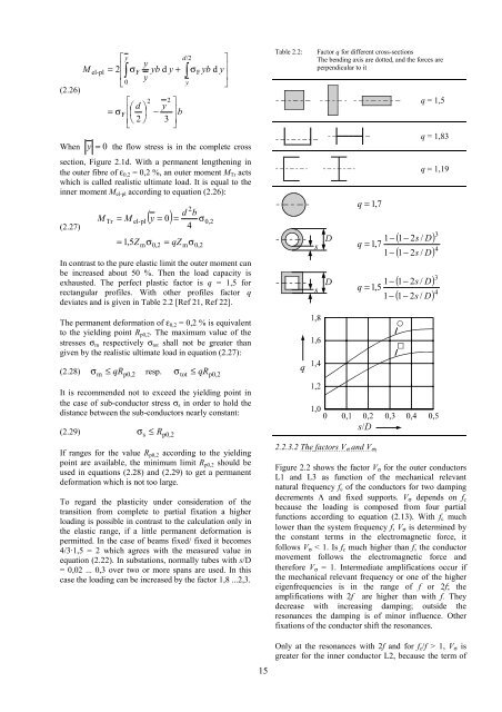
Table 2.2: Factor q for different cross-sections<br />
<strong>The</strong> bend<strong>in</strong>g axis are dotted, and the forces are<br />
perpendicular to it<br />
q = 1,<br />
7<br />
1−<br />
q = 1,<br />
7<br />
1−<br />
1−<br />
q = 1,<br />
5<br />
1−<br />
2.2.3.2 <strong>The</strong> factors V<br />
σ and V<br />
σs<br />
q = 1,5<br />
q = 1,83<br />
q = 1,19<br />
( )<br />
( ) 4<br />
3<br />
1−<br />
2s<br />
/ D<br />
1−<br />
2s<br />
/ D<br />
( )<br />
( ) 4<br />
3<br />
1−<br />
2s<br />
/ D<br />
1−<br />
2s<br />
/ D<br />
Figure 2.2 shows the factor Vσ for the outer conductors<br />
L1 and L3 as function <strong>of</strong> the <strong>mechanical</strong> relevant<br />
natural frequency fc <strong>of</strong> the conductors for two damp<strong>in</strong>g<br />
decrements Λ and fixed supports. Vσ depends on fc<br />
because the load<strong>in</strong>g is composed from four partial<br />
functions accord<strong>in</strong>g to equation (2.13). With fc much<br />
lower than the system frequency f, Vσ is determ<strong>in</strong>ed by<br />
the constant terms <strong>in</strong> the electromagnetic force, it<br />
follows Vσ < 1. Is fc much higher than f, the conductor<br />
movement follows the electromagnetic force and<br />
therefore Vσ = 1. Intermediate amplifications occur if<br />
the <strong>mechanical</strong> relevant frequency or one <strong>of</strong> the higher<br />
eigenfrequencies is <strong>in</strong> the range <strong>of</strong> f or 2f; the<br />
amplifications with 2f are higher than with f. <strong>The</strong>y<br />
decrease with <strong>in</strong>creas<strong>in</strong>g damp<strong>in</strong>g; outside the<br />
resonances the damp<strong>in</strong>g is <strong>of</strong> m<strong>in</strong>or <strong>in</strong>fluence. Other<br />
fixations <strong>of</strong> the conductor shift the resonances.<br />
Only at the resonances with 2f and for fc/f > 1, Vσ is<br />
greater for the <strong>in</strong>ner conductor L2, because the term <strong>of</strong>


