

The mechanical effects of short-circuit currents in - Montefiore
The mechanical effects of short-circuit currents in - Montefiore
The mechanical effects of short-circuit currents in - Montefiore

You also want an ePaper? Increase the reach of your titles
YUMPU automatically turns print PDFs into web optimized ePapers that Google loves.
a) b)<br />
F m<br />
c)<br />
F m<br />
O<br />
d d d d d<br />
O<br />
OT O<br />
d d d D d d<br />
O T<br />
O<br />
O T<br />
O T<br />
d<br />
d<br />
b<br />
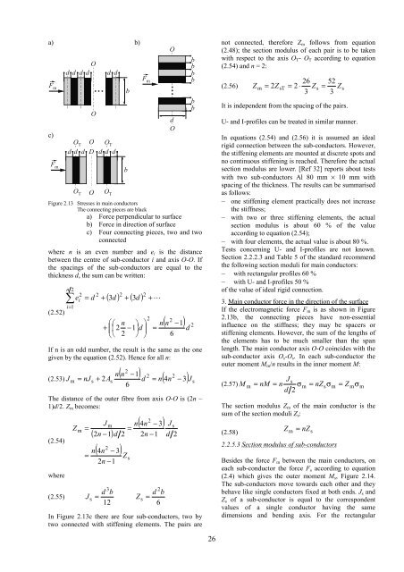
Figure 2.13 Stresses <strong>in</strong> ma<strong>in</strong> conductors<br />
<strong>The</strong> connect<strong>in</strong>g pieces are black<br />
a) Force perpendicular to surface<br />
b) Force <strong>in</strong> direction <strong>of</strong> surface<br />
c) Four connect<strong>in</strong>g pieces, two and two<br />
connected<br />
where n is an even number and ei is the distance<br />
between the centre <strong>of</strong> sub-conductor i and axis O-O. If<br />
the spac<strong>in</strong>gs <strong>of</strong> the sub-conductors are equal to the<br />
thickness d, the sum can be written:<br />
b<br />
F m<br />
n 2<br />
2 2 2 2<br />
∑ ei<br />
= d + ( 3d<br />
) + ( 3d<br />
) + L<br />
i=<br />
1<br />
(2.52)<br />
2<br />
⎛⎛<br />
n ⎞ ⎞ n<br />
+ ⎜⎜<br />
2 −1⎟d<br />
⎟ =<br />
⎝⎝<br />
2 ⎠ ⎠<br />
O<br />
d<br />
O<br />
b<br />
b<br />
b<br />
b<br />
b<br />
b<br />
2 ( n −1)<br />
2<br />
If n is an odd number, the result is the same as the one<br />
given by the equation (2.52). Hence for all n:<br />
n(<br />
n −1)<br />
2 2<br />
(2.53) J m = nJ s + 2As d = n(<br />
4n<br />
− 3)<br />
J s<br />
6<br />
<strong>The</strong> distance <strong>of</strong> the outer fibre from axis O-O is (2n –<br />
1)d/2. Zm becomes:<br />
(2.54)<br />
where<br />
Z<br />
m<br />
=<br />
J<br />
m<br />
( 2n<br />
−1)<br />
2 ( 4n<br />
− 3)<br />
n<br />
=<br />
2n<br />
−1<br />
3<br />
2<br />
Z<br />
s<br />
2 ( 4n<br />
− 3)<br />
n<br />
=<br />
d 2 2n<br />
−1<br />
d b<br />
d b<br />
(2.55) J s = Zs<br />
=<br />
12<br />
6<br />
In Figure 2.13c there are four sub-conductors, two by<br />
two connected with stiffen<strong>in</strong>g elements. <strong>The</strong> pairs are<br />
2<br />
d<br />
J<br />
6<br />
s<br />
2<br />
d<br />
26<br />
not connected, therefore Zm follows from equation<br />
(2.48); the section modulus <strong>of</strong> each pair is to be taken<br />
with respect to the axis OT- OT accord<strong>in</strong>g to equation<br />
(2.54) and n = 2:<br />
Z = 2Z 26<br />
= 2 ⋅ Z<br />
3<br />
52<br />
= Z<br />
3<br />
It is <strong>in</strong>dependent from the spac<strong>in</strong>g <strong>of</strong> the pairs.<br />
(2.56) m sT<br />
s s<br />
U- and I-pr<strong>of</strong>iles can be treated <strong>in</strong> similar manner.<br />
In equations (2.54) and (2.56) it is assumed an ideal<br />
rigid connection between the sub-conductors. However,<br />
the stiffen<strong>in</strong>g elements are mounted at discrete spots and<br />
no cont<strong>in</strong>uous stiffen<strong>in</strong>g is reached. <strong>The</strong>refore the actual<br />
section modulus are lower. [Ref 32] reports about tests<br />
with two sub-conductors Al 80 mm × 10 mm with<br />
spac<strong>in</strong>g <strong>of</strong> the thickness. <strong>The</strong> results can be summarised<br />
as follows:<br />
– one stiffen<strong>in</strong>g element practically does not <strong>in</strong>crease<br />
the stiffness;<br />
– with two or three stiffen<strong>in</strong>g elements, the actual<br />
section modulus is about 60 % <strong>of</strong> the value<br />
accord<strong>in</strong>g to equation (2.54);<br />
– with four elements, the actual value is about 80 %.<br />
Tests concern<strong>in</strong>g U- and I-pr<strong>of</strong>iles are not known.<br />
Section 2.2.2.3 and Table 5 <strong>of</strong> the standard recommend<br />
the follow<strong>in</strong>g section moduli for ma<strong>in</strong> conductors:<br />
– with rectangular pr<strong>of</strong>iles 60 %<br />
– with U- and I-pr<strong>of</strong>iles 50 %<br />
<strong>of</strong> the value <strong>of</strong> ideal rigid connection.<br />
3. Ma<strong>in</strong> conductor force <strong>in</strong> the direction <strong>of</strong> the surface<br />
If the electromagnetic force Fm is as shown <strong>in</strong> Figure<br />
2.13b, the connect<strong>in</strong>g pieces have non-essential<br />
<strong>in</strong>fluence on the stiffness; they may be spacers or<br />
stiffen<strong>in</strong>g elements. However, the sum <strong>of</strong> the lengths <strong>of</strong><br />
the elements has to be much smaller than the span<br />
length. <strong>The</strong> ma<strong>in</strong> conductor axis O-O co<strong>in</strong>cides with the<br />
sub-conductor axis Os-Os. In each sub-conductor the<br />
outer moment Mm/n results <strong>in</strong> the <strong>in</strong>ner moment M:<br />
J<br />
d 2<br />
s<br />
(2.57) M m = nM = n σm<br />
= nZsσ<br />
m = Z mσ<br />
m<br />
<strong>The</strong> section modulus Zm <strong>of</strong> the ma<strong>in</strong> conductor is the<br />
sum <strong>of</strong> the section moduli Zs:<br />
(2.58)<br />
Z m = nZs<br />
2.2.5.3 Section modulus <strong>of</strong> sub-conductors<br />
Besides the force Fm between the ma<strong>in</strong> conductors, on<br />
each sub-conductor the force Fs accord<strong>in</strong>g to equation<br />
(2.4) which gives the outer moment Ms, Figure 2.14.<br />
<strong>The</strong> sub-conductors move towards each other and they<br />
behave like s<strong>in</strong>gle conductors fixed at both ends. Js and<br />
Zs <strong>of</strong> a sub-conductor is equal to the correspondent<br />
values <strong>of</strong> a s<strong>in</strong>gle conductor hav<strong>in</strong>g the same<br />
dimensions and bend<strong>in</strong>g axis. For the rectangular


